18
Before you start
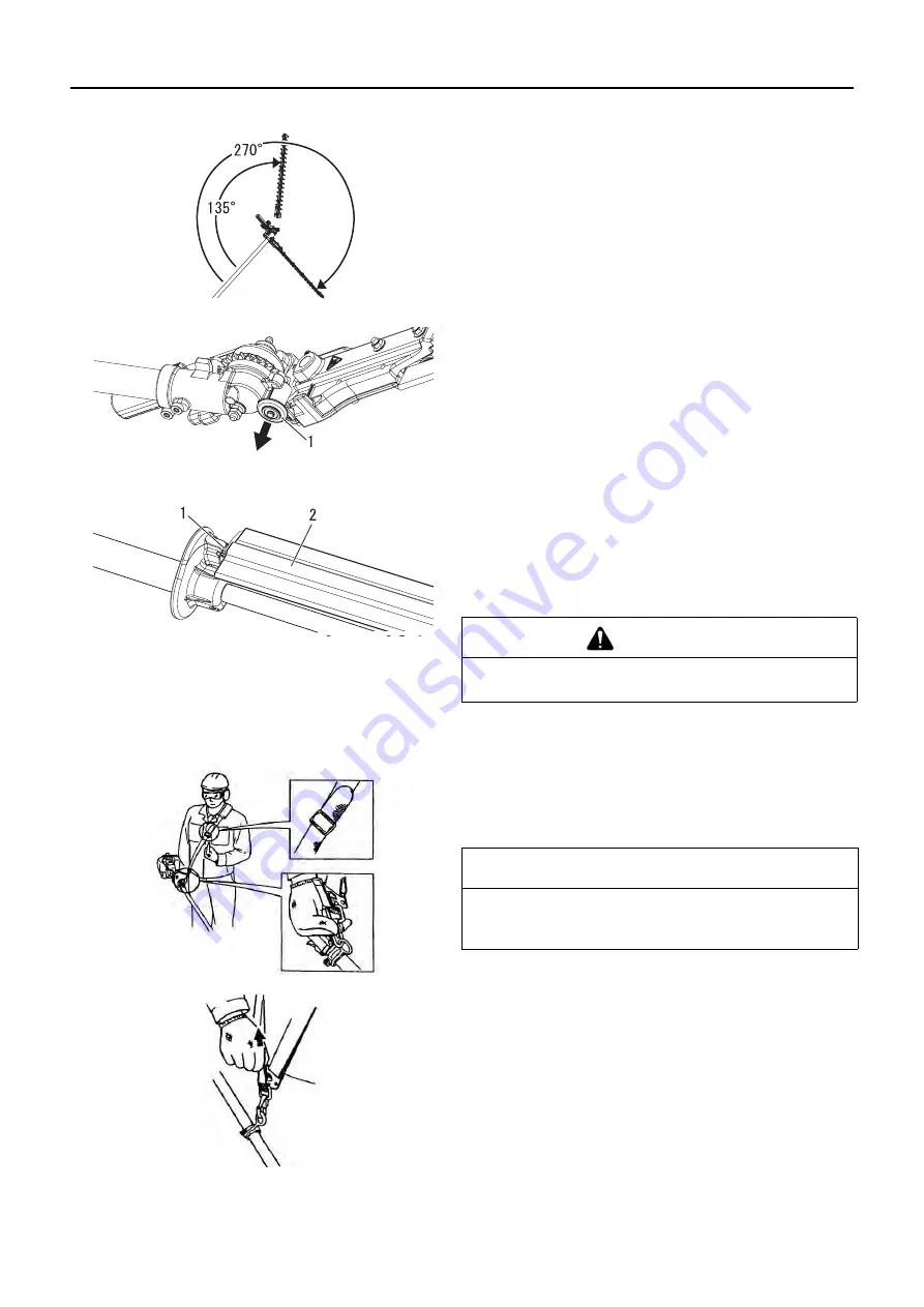
Cutter assembly position
The cutter assembly can be adjusted to ten different positions
ranging from 135° to 270° from the outer tube as shown. Al-
ways make sure the lock latch is securely locked after each
adjustment.
Adjusting for Storage or Transportation
1. With the engine off, install the blade cover onto the blade.
2. Rotate the cutter assembly so it is parallel to the tube. The
rotation is restricted at the position of 135° by the lock pin.
Pull the knob and release the lock pin.
3. Make sure the latch lock and the latch release return secure-
ly to a locking position.
4. Fit the tip of the cutter assembly into the storage position of
the hand guard and fix it.
5. Make sure the blade cover is in place on the cutters before
storing or transporting.
Shoulder strap
1. Hook the strap hook to the hanger on the outer tube.
2. Wear the shoulder strap so that the hook stays at your right
hand side.
3. Adjust the length of the shoulder strap so that you can hold
and operate the machine comfortably.
Emergency Release
∗
In case of emergency, strongly pull the white tab at the hook.
The machine will be released from the strap.
1. Knob
1. Support notch
2. Blade cover
WARNING
Never run the engine when adjusting the cutter assem-
bly to the storage position.
IMPORTANT
Adjust the shoulder strap or harness so the shoulder pad rests
comfortably on the off-side shoulder. Make sure all hooks and
adjustment devices are secure.


