background image

7)  Apply Petroleum jelly  to the inside of the piston cylinder wall
and on the collar, and reinstall the piston assembly into the piston
cylinder.

8) Insert the piston at an angle with the leading edge of the
collar placed over the slot in the piston cylinder. Bolt the piston
assembly to the pump shaft using the lever bolts.

9) Replace the protective dust cap. Tighten the
nut and bolt. Reinstall the pump handle. Replace the hose
and firmly secure the hose clamp in place.

8E

Figure 9

Figure 8

Figure 7

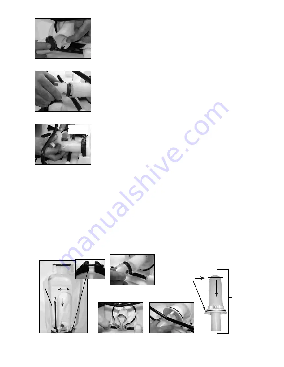
Only remove the pump assembly if the cartridge filter  is clogged or the sprayer is leaking
between the pressure chamber o-ring and tank.

  DISASSEMBLING AND REPAIRING THE PUMP ASSEMBLY

1.  Release the pressure from the sprayer and remove all liquid from both the pressure chamber and tank.
2. Remove hose.
3. Remove the In-tank filter from the pressure cylinder (located inside the tank - fig. 1).
4. Remove 2 bolts attaching the pivot lever to the pump shaft and remove piston assembly (fig. 2a & 2b).
5. Remove the large clamp holding the pressure chamber and tank together (fig 1).
6. Rock the pressure chamber back and forth and push down to free it from the tank (fig 1).
7. Once freed the entire pump assembly can be removed by maneuvering it through the base frame

(fig 3a & 3b).

B

Clamp

Figure 2b

Figure 3a

Figure 1

Figure 2a

Protective

Dust Cap

Figure 3b

Pressure
Chamber o-ring

Pump
Assembly

5F

INFORMATION D'UTILISATION ET COMPOSANTS DU PULVÉRISATEUR, suite

INFORMATION UTILE SUR LA PULVÉRISATION

Utilisez des mouvements de pompage RAPIDES pour amorcer la pompe.Vous saurez que la chambre de
pression se remplit de liquide en sentant une résistance prononcée de la pompe. L'air de la chambre de
pression se comprime suite à des mouvements répétés du piston. En appuyant sur le levier à main, sur la
soupape d'arrêt, la soupape s'ouvre. Pour la fonction de verrouillage désactivé de sécurité (sans pulvérisation),
relevez la poignée et déplacez le mécanisme de verrouillage rouge en position de verrouillage comme indiqué
dans la fig. 1.  Pour désengager, enfoncez la poignée et remettez le mécanisme de verrouillage rouge à la
position neutre comme dans la fig. 3.  Pour la fonction de verrouillage (pulvérisation continue), enfoncez la
poignée et déplacez le mécanisme de verrouillage rouge en position de verrouillage comme indiqué dans la fig.
2. Pour désengager, enfoncez la poignée et remettez le mécanisme de verrouillage rouge à la position neutre
comme dans la fig. 3.

Pour faciliter le pompage, utilisez l'EXTRÉMITÉ de la poignée de la pompe. La quantité de liquide livré par la
pulvérisation dépend du rythme des mouvements de pompage. L'embout de gicleur de ventilateur est évalué à
.4 gal/mn à 40psi. C'est la pression de fonctionnement nominale du pulvérisateur.

Remarque:

 si vous voyez une chute de pression rapide, drainez entièrement le pulvérisateur et actionnez la

poignée alors que la cuve est vide. La chambre de pression se remplira du volume d'air requis pour une
recompression. Exécutez ce procédé de temps en temps en tant qu'entretien régulier.

PRODUITS CHIMIQUES À BASE DE POUDRE

Les produits chimiques à base de poudre (poudre mélangée aux liquides pour former l'agent de pulvérisation)
sont normalement abrasifs et peuvent provoquer l'usure. Lorsque vous utilisez ces produits chimiques dans
votre pulvérisateur, assurez-vous qu'ils soient bien dissous dans la solution liquide. Nettoyez et rincez bien le
pulvérisateur avec de l'eau pour prolonger la durée de vie utile de ses pièces.

NETTOYAGE

1) Videz toujours le pulvérisateur et nettoyez bien la cuve après chaque utilisation.
2) Actionnez la poignée du pulvérisateur jusqu'à ce que tout le contenu et l'air sortent par la buse (minimum de
30 rappes).
3) Remplissez la moitié de la cuve d'eau et pompez pour extraire l'eau tel qu'expliqué à l'étape 2 (répétez
plusieurs fois si nécessaire).

Autres conseils de nettoyage :

• Une mauvaise répartition de la pulvérisation signifie normalement que la buse est obstruée; retirez-la
   et nettoyez-la.
• Vous pouvez ajouter du savon à l'eau pour nettoyer la cuve.
• Par contre, n'utilisez pas d'agents de nettoyage puissants ou d'abrasifs.
• Si vous utilisez un agent chimique pour nettoyer la cuve, suivez les recommandations du fabricant pour
   l'élimination de l'eau usée.
• Suivez toujours les instructions du fabricant de produits chimiques pour le nettoyage.

POSITION DE LOCK-OFF

POSITION DE VERROUILLAGE

LA POSITION NEUTRE

Figure 1

Figure 2

Figure 3

In-tank Filter

Si el cierre falla, coloque la vara en el tanque hasta que la presión se agote totalmente.

Summary of Contents for MS-40BP

Page 1: ...011289 R0211 Carefully Read These Instructions Before Use WARNING Model MS 40BP 4 0G 15 1L Use and Care Manual Backpack ...

Page 2: ...zed sprayer in the hot sun or anywhere near a heat source Heat can produce pressure to build up causing sprayer to ignite or explode resulting in injury or death NEVER pressurize sprayer by any means other than the original pump Over pressurizing can cause sprayer to explode resulting in injury or death DO NOT attempt to modify or repair this product except with original manufacturer s parts NOTE ...

Page 3: ...but avoid using the same sprayer for plant feeding or protection without thoroughly cleaning see cleaning section the sprayer first General Household Use Apply detergents vinegar cleaning solutions warm water do not exceed 120 F 49 C or nontoxic household cleaning chemicals for carpets floors walls glass counter tops and ceilings DO NOT use sprayer that has been used with herbicides pesticides or ...

Page 4: ...he tank Attach the lower end of the straps by clipping the strap hooks to the metal frame between where the frame exits the tank and curves around NOTE If your straps become contaminated with dirt or chemicals wash with mild soap and water and let dry overnight If this does not remove the contamination replace with new straps WAND CLIP The wand can be attached to the pump handle using the wand cli...

Page 5: ... removable filter incorporated into the inlet side of the shut off valve see section disassembling and repairing the shut off valve Make sure pressure is released before detaching the hose from the shut off It is best to have no or minimal fluid in the pressure cylinder before removing and reinstalling the stage 4 shut off filter as fluid can leak from the hose Stage 1 filter basket Stage 2 remova...

Page 6: ...e tank thoroughly after each use 2 Pump the sprayer handle until all of the contents and air exit through the nozzle minimum of 30 strokes 3 Fill tank half way with water and pump the water out as explained in step 2 repeat several times as necessary Other Cleaning Hints Improper spray distribution usually means the nozzle is clogged remove the nozzle and clean it Soap can be added to the water to...

Page 7: ...cushion in the pressure Release pressure in pressure chamber pumping strokes but pressure only lasts chamber Remove the hose drain pressure briefly chamber Reconnect the hose Upper valve plate damaged worn dirty Clean or replace upper valve plate Upward pumping action is more difficult Vent hole is clogged Clear the vent hole in cap and orpump handle moves itself backdown Lower valve plate sticks ...

Page 8: ...t get any grease on the valve plate and screw the piston assembly into the pressure cylinder base Screw the piston cylinder clockwise until tight and the bottom O ring is no longer visible When properly placed the tab on the piston cylinder will line up with the rib on the pressure cylinder base DISASSEMBLING AND REPAIRING THE PISTON PUMP Figure 1 7E 5 There are 2 valve plates on the piston cylind...

Page 9: ...etween the pressure chamber o ring and tank DISASSEMBLING AND REPAIRING THE PUMP ASSEMBLY 1 Release the pressure from the sprayer and remove all liquid from both the pressure chamber and tank 2 Remove hose 3 Remove the In tank filter from the pressure cylinder located inside the tank fig 1 4 Remove 2 bolts attaching the pivot lever to the pump shaft and remove piston assembly fig 2a 2b 5 Remove th...

Page 10: ...EMBLING AND REPAIRING THE SHUT OFF VALVE 9E Figure 5 8 At this point the filter cartridge in the pressure chamber base can be removed with pliers and cleaned fig 4 9 The pressure chamber o ring can also be replaced DO NOT stretch the o ring over the bottom flange Assemble the o ring over the top of the chamber Apply petroleum jelly to the o ring before reinstalling pump asembly into the tank fig 3...

Page 11: ...Y 99944100484 Flat Fan Nozzle 99944100483 Poly Adjustable Nozzle 99944100482 Brass Adjustable Nozzle Screw Cap O ring 99944100480 Wand Assembly Wand 99944100478 Shut off Assembly 99944100481 Filter Replacement Kit 99944100479 Hose Assembly Hose Washer Retaining Nut Hose 99944100485 Nozzle Kit ...

Page 12: ...ssembly 99944100474 Piston Cylinder Assembly 99944100473 Filter Basket Cap 99944100471 Piston Pump Repair Kit O ring Piston Cylinder O ring Pressure Chamber Collar Pump Piston Valve Plate Piston Cylinder 99944100472 Straps A F D in jo in F D d APPL É p u d N fe H p d U n r N t U d d s INFOR 1 ASSEM 1 Assu le ro 2 Tour 99944100489 Pump Handle ECHO INCORPORATED 400 Oakwood Road Lake Zurich IL 60047 ...

Page 13: ...n a piston pump sprayer Wear items including but not limited to seals gaskets pistons hoses diaphragms straps or any wear item These items are covered for 90 days from date of purchase Any mis use of product is not covered including but not limited to using un approved chemicals or parts un approved uses using damaged or missing units parts during operation or modifying your sprayer in any manner ...

Reviews: