background image

P

OWER

 E

DGER

O

PERATOR

'

S

 M

ANUAL

5

EXTENDED


OPERATION

/

EXTREME


CONDITIONS

Vibration and Cold

It is believed that a condition called Raynaud’s Phenomenon, which
affects the fingers of certain individuals, may be brought about by
exposure to vibration and cold. Exposure to vibration and cold may
cause tingling and burning sensations, followed by loss of color and
numbness in the fingers. The following precautions are strongly
recommended, because the minimum exposure which might trigger the
ailment is unknown.

• Keep your body warm, especially the head, neck, feet, ankles, hands,

and wrists.

• Maintain good blood circulation by performing vigorous armexercises

during frequent work breaks, and also by not smoking.

• Limit the hours of operation. Try to fill each day with jobs where

operating the edger or other hand-held power equipment is not
required.

• If you experience discomfort, redness, and swelling of the fingers,

followed by whitening and loss of feeling, consult your physician
before further exposing yourself to cold and vibration.

Repetitive Stress Injuries

It is believed that overusing the muscles and tendons of the fingers,
hands, arms, and shoulders may cause soreness, swelling, numbness,
weakness, and extreme pain in those areas.  Certain repetitive hand
activities may put you at a high risk for developing a Repetitive Stress
Injury (RSI). An extreme RSI condition is Carpal Tunnel Syndrome
(CTS), which could occur when your wrist swells and squeezes a vital
nerve that runs through the area. Some believe that prolonged exposure
to vibration may contribute to CTS. CTS can cause severe pain for
months or even years.

To reduce the risk of RSI/CTS, do the
following:

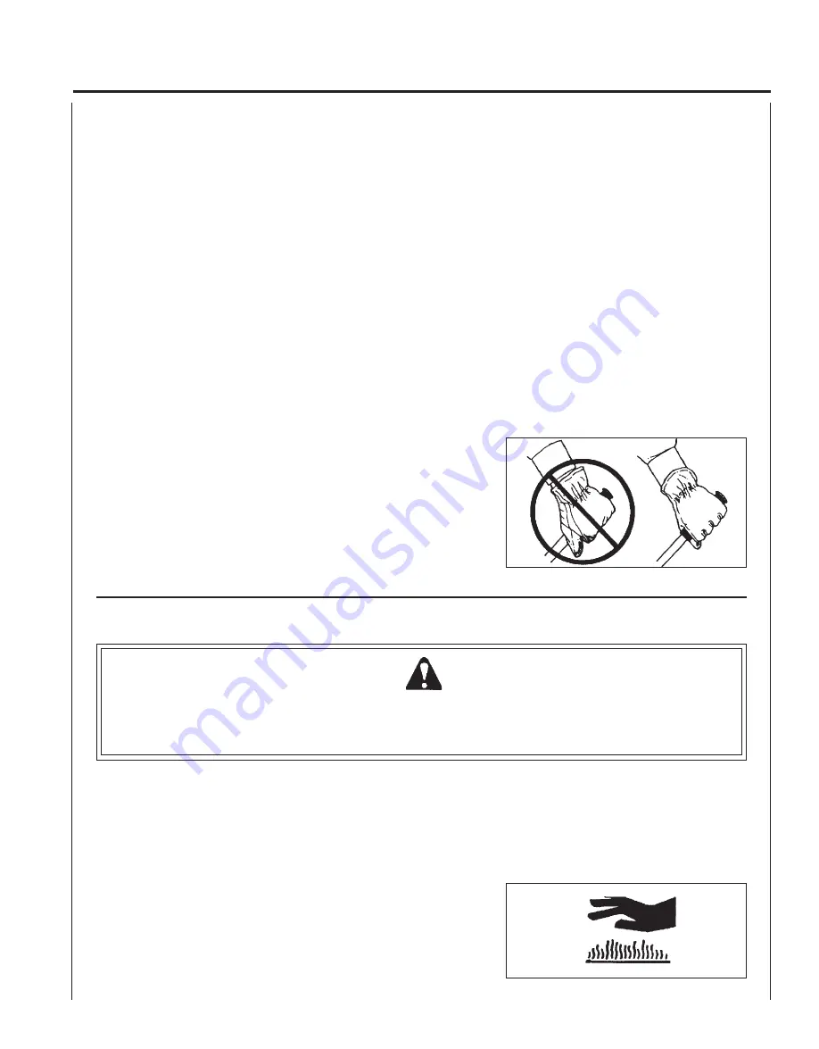
• Avoid using your wrist in a bent, ex-

tended, or twisted position. Instead, try to
maintain a straight wrist position.  Also,
when grasping, use your whole hand, not
just the thumb and index finger.

• Take periodic breaks to minimize repetition

and rest your hands.

• Reduce the speed and force with which

you do the repetitive movement.

• Do exercises to strengthen the hand and

arm muscles.

• Immediately stop using all power equip-

ment and consult a doctor if you feel
tingling, numbness, or pain in the fingers,
hands, wrists, or arms. The sooner RSI/
CTS is diagnosed, the more likely perma-
nent nerve and muscle damage can be
prevented.

EQUIPMENT

 • Check unit for loose/missing nuts, bolts and screws. Tighten and/or

replace as needed.

• Inspect fuel lines, tank, and area around carburetor for fuel leaks. DO

NOT operate unit if leaks are found.

• Inspect shield for damage, and that shield is securely in place.

Replace if shield is damaged or missing.

• Check that the cutting attachment is firmly attached and in safe

operating condition.

• Check that front handle is adjusted for safe, comfortable operation.

See Assembly for proper adjustment.

• Keep exhaust area clear of flammable debris. Avoid contact during

and immediately after operation.

WARNING   

   DANGER

Use only ECHO approved attachments. Serious injury may result from the use of a non approved attachment
combination. ECHO, INC. will not be responsible for the failure of cutting devices, attachments or accessories which
have not been tested and approved by ECHO. Read and comply with all safety instructions listed in this manual and
safety manual.

Summary of Contents for PE-200

Page 1: ...PE 200 Serial Number 05001001 05045500 X770000680 03 03 X7702275300 WARNING DANGER Readrulesforsafeoperationandinstructionscarefully ECHOprovidesan Operator sManualandaSafetyManual Bothmustbereadandu...

Page 2: ...arranty Card 24 Additional or Replacement Manuals 24 Specifications descriptions and illustrative material in this literature are as accurate as known at the time of publica tion but are subject to ch...

Page 3: ...nd helpful informational messages preceded by symbols or key words The following is an explanation of those symbols and key words and what they mean to you This symbol accompanied by the words WARNING...

Page 4: ...h speed mixture Emergencystop Carburetor adjustment Low speed mixture Wearslip resistant foot wear Ignition ON OFF Primerbulb Keepfeetaway from blade Thrown objects Direction of blade CHOKE CONTROL CO...

Page 5: ...ged exposure to vibration may contribute to CTS CTS can cause severe pain for months or even years To reduce the risk of RSI CTS do the following Avoid using your wrist in a bent ex tended or twisted...

Page 6: ...Do not over reach EMISSION CONTROL EPA Phase 2 The emission control system for these engines are EM Engine Modification PRODUCT EMISSION DURABILITY The 300 hour emission durability compliance period...

Page 7: ...e contents list to check for missing parts CONTENTS __ 1 Edger Drive Shaft Assembly __ 1 PowerHead __ 1 PlasticBag Co Pack __ 1 Operator s Manual __ 1 Safety Manual __ 1 Warranty Registration Card __...

Page 8: ...P 12 CHOKE The choke control is located on the air filter case Move lever to COLD START to close choke for cold starting Move lever to RUN position to open choke 13 SPARK PLUG Providessparktoignitefue...

Page 9: ...ixed GasolineandTwo strokeOil Fuel OilRatio 50 1 two stroke air cooled engine oil Gasoline 89 Octane unleaded DO NOT use fuel containing methyl alcohol more than 10 ethyl alcohol or 15 MTBE Oil PowerB...

Page 10: ...olts A THROTTLE LINKAGE 1 Place throttle linkage B through adjustment fixture C and install wire end into large carburetor throttle swivel hole D Check throttle for freedom of movement and that wide o...

Page 11: ...arewhenmixing storingor handling or serious personal injury may result Use an approved fuel container DONOTsmokenearfuel DO NOT allow flames or sparks near fuel Fuel tanks cans may be under pressure A...

Page 12: ...4 Recoil Starter Lay the unit on a flat area and keep movable attachment parts clear of all obstacles Firmly grasp right hand grip with left hand and fully depress throttle trigger to wide open positi...

Page 13: ...C until fuel will be visible and flows freely in the clear fuel tank return line Pump bulb an additional 4 or 5 times 3 Recoil Starter Lay the unit on a flat area and keep movable attachment parts cle...

Page 14: ...3 mm 1 2 in of the blade into the ground 5 Before edging plan your direction of travel so that the unit will always be positioned on your right side and so that you walk on a hard surface whenever pos...

Page 15: ...t r o P t s u a h x E r e d n i l y C n o b r a c e D n a e l C t c e p s n I 3 C I s e r u d e c o r P e c n a n e t n i a M f l e s r u o Y t I o D r e t l i F r i A e c a l p e R n a e l C t c e p...

Page 16: ...f element can be cleaned and reused be certain it still fits the cavity in the air cleaner cover is installed with the original side out FUEL FILTER Level1 Tools required 200 250mm 8 10in lengthofwire...

Page 17: ...CrossHeadScrewdriver 3mmHexWrench Cleaning Brush25or50mm 1or2in Parts Required None if you are careful IMPORTANT To maintain proper engine operating temperatures cooling air must pass freely through...

Page 18: ...grass and leaves from the grid between the recoil starter and fuel tank 6 Assemble components in reverse order NOTE When installing the cover be certain the tab of the deflector shield is in the slot...

Page 19: ...justment is not required for proper operation of this engine Level2 Tools required Screwdriver Tachometer ECHOP N99051130017 Parts required None NOTE Every unit is run at the factory and the carbureto...

Page 20: ...nd gear box align Insert locking tool to lock PTO shaft C NOTE Shield cover not shown for illustration clarity NOTE Blade nut D is left hand thread 4 Remove blade nut D in a clockwise direction using...

Page 21: ...e l a e d o h c E r u o y e e S r e l a e d o h c E r u o y e e S g u l p t a k r a p S k r a p s o N t c e r r o c n i p a g k r a p S n o b r a c h t i w d e r e v o C l e u f h t i w d e l u o F e...

Page 22: ...or spark 2 Place the stop switch in the STOP position 3 Remove accumulation of grease oil dirt and debris fromexteriorofunit 4 Perform all periodic lubrication and services that are required 5 Tighten...

Page 23: ...POWER EDGER OPERATOR S MANUAL 23 NOTES...

Page 24: ...now the model and serial number of your unit to help your Consumer Product Support Representative WARRANTY REGISTRATION You may register your Echo equipment using the warranty registration card or reg...

Reviews: