


15
Assembling
U-handle installation
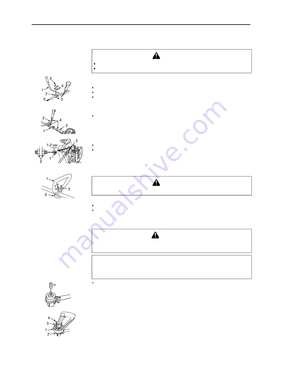
1. U-handle 2. Handle bracket 3. Two bolts (M5x25) 4. Handle bar suppoet
5. Four bolts (M5x25) 6. To engine
Loosen handle bracket and handle bar support bolts.
Locate handle bar in a comfortable operating position and tighten bolts (M5x25) lightly.
Adjust inclination of handle to adequate position (easy to operate) and tighten firmly handle
assembling bolts (M5x25).
1. Throttle wire 2. Shaft tube 3. Right hand U-handle 4. Wire fixing clip
To eliminate loosening of throttle wire fix it to shaft tube (2 places) and to right hand
U-handle (1 place) with wire fixing clips.
1. Wire end 2. Nuts 3. Carburettor
Check that throttle operates freely and returns to idle position.
Adust the play of wire end on carburettor side to 1 - 2 mm.
Front (loop) handle installation
1. Front (Loop) handle 2. Handle bracket 3. Four screws (M5x35)
Position handle in comfortable operating position and tighten screws (M5x35).
The cutting attachment should be 5 - 7.5 cm above the ground and as level as possible.
Plastic shield installation
(For nylon line operation)
Plastic sleeve
1) Remove plastic sleeve from output shaft.
1. Shield 2. Angle transmission flange 3. Shield plate 4. Three screws (M5x16)
2) Install the shield on the bottom of the angle transmission flange.
3) Place shield plate on shield, align holes and install three screws (M5x16).
4) Tighten firmly three screws.
CAUTION
Install the handle so that it does not hide any of the safety decals.
After assembly, adjust the play of wire end on carburettor side to 1 - 2 mm.
CAUTION
Install the handle so that it does not hide any of the safety decals.
WARNING
Cut off knife on debris shield has sharp edges.
Avoid contact when installing or removing line head.
NOTE
The plastic shield is for use with the nylon line head only.
Install metal shield when using plastic or metal blades.


