background image

Echoflex Installation Guide

Access Interface

Connect Wiring

1. Pull all required wiring into the back box. As needed, pull an

additional ESD ground wire (required only when the Interface is not
installed in grounded metal conduit).

2. Terminate the ESD ground wire pigtail.

a. Strip 11 mm (0.4 in) of insulation from the ends of the ESD ground

wire pigtail provided in the termination supplies and the incoming
ground wire.

b. Use one WAGO 221 Series LEVER-NUTS

®

(provided) to connect the

ESD ground pigtail and the incoming ground. Installations using
grounded metal conduit, connect the ground pigtail to the metal
back box ground location.

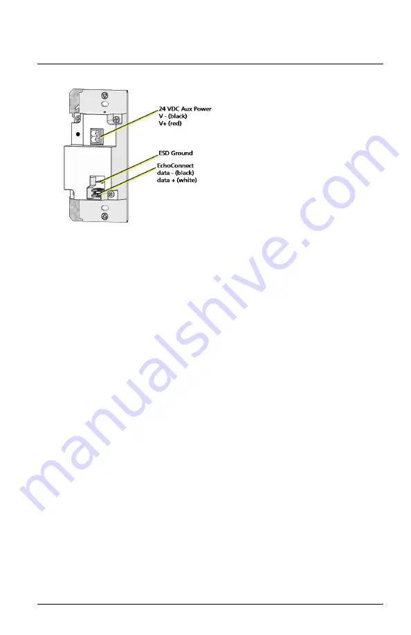
c. Install the ESD ground wire pigtail FASTON connector to the

mating receptacle on the Interface electronics.

3. Terminate EchoConnect wires. EchoConnect is topology free, you

may install the wires in any combination of bus, star, loop, or home-
run.

a. Strip 11 mm (0.4 in) from the ends of each EchoConnect power

pigtail wire (black and white wire pair), provided in the
termination supplies, and the installed control wires.

b. Use the WAGO connectors (provided) to connect the EchoConnect

pigtail wires and the installed Belden 8471 control wires. One
WAGO should be used for the white wire pair (data +) and one for
the black wire pair (data -). Open the terminal levers on the WAGO
connector and insert the installed Belden 8471 wire and the lead
from the power pigtail into the terminals, and then close the
levers.

c. Install the two-pin connector from the EchoConnect pigtail to the

mating receptacle on the station electronics.

Access Interface

Page 3 of 8

Echoflex

Summary of Contents for ElahoAccess

Page 1: ...figure and control your Elaho Presets Spaces Zones and devices Specification Installation Environment For indoor commercial controls use only Echoflex recommends paying special attention to the instal...

Page 2: ...25 4 cm 10 in of wiring in the back box for connection and to allow slack for future service needs Note Echoflex requires that all stations and devices be grounded for ESD protection Pull an additiona...

Page 3: ...he mating receptacle on the Interface electronics 3 Terminate EchoConnect wires EchoConnect is topology free you may install the wires in any combination of bus star loop or home run a Strip 11 mm 0 4...

Page 4: ...ed to connect the Auxiliary pigtail wires and the power wires One WAGO should be used for the red wire pair V and one for the black wire pair V Open the terminal levers on the WAGO connector and inser...

Page 5: ...ng the mounting screws provided If using spacers insert the screws through the spacers as well Interface LEDs Power The top blue LED lights when the device has power Bluetooth The bottom yellow LED li...

Page 6: ...cure Note If you are installing a multi gang wall plate and the stations are misaligned in the mounting box the wall play will not attach properly Loosen the screws that secure the station to the back...

Page 7: ...e of the following measures Reorient or relocate the receiving antenna Increase the separation between the equipment and receiver Connect the equipment into an outlet on a circuit different from that...

Page 8: ...own expense This device contains a wireless module with the following identification numbers FCC ID T9JRN4020 ISED Compliance This device contains a license exempt transmitter receiver that complies...

Reviews: