5
within range of the temperature sensor to be linked.
The sensor is a solar powered device that absorbs energy through a solar
panel storing it for use during low light periods. Before assigning the sensor to
a receiver/controller, the device must be exposed to a good light source for a
minimum of 2 hours, or install the optional start assist battery (not supplied).
1. Remove the sensor from the back plate by pressing in
on the tab on the lower edge and pulling away from
the back plate.
2.
Activate LEARN or LINK mode at the receiver, if
necessary refer to the manufacturers documentation.
3.
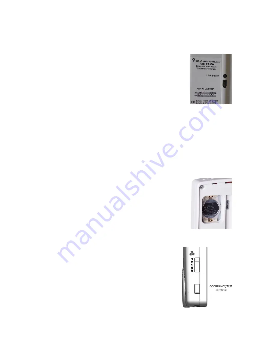
Press the temperature sensors Link (Teach) button.
4. Deactivate LEARN mode at the receiver.
Installing or Replacing the Battery
The battery is not required for normal operation when the RTS receives
adequate natural or artificial light. The battery can be used during installation
(start assist).
1. Remove the sensor from the back plate by pressing the key on the lower
edge of the sensor body and pull the body away from the back plate.
2.
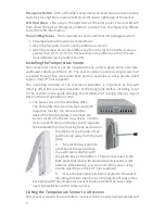
To remove old battery: Using a small flat head screwdriver or pen as a lever,
insert pointed end under the clear plastic battery retaining clip’s edge and
pop the clip off.
3.
Install or replace the battery in the clip with a new
CR2032 coin cell battery insuring the positive side (+)
will be facing up.
4.
Align the two straight edges of the retaining clip with
the battery holder and press the clip in with your
finger.
Test Operating Modes
Ensure the RTS is fully charged before entering test modes. Inserting a battery
during test modes is also recommended. The following tests can be selected
when in test mode.
Light Level Test:
provides visual feedback of the
immediate energy produced by the solar panel.
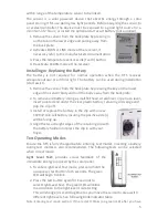
1. To enter Light Level Test mode, press and hold the
occupancy/ test button for 6 seconds. The green
LED will begin to blink.
2.
Press the test button again for 6 seconds to
select Light Level Test. The green LED will blink
in accordance to the light level it is detecting.
This will change (2 second lag time) as you move the sensor to areas with
different light levels. See following blink indicator table.
Note: Entering test mode section: If the red LED blinks (no green LED) after you have


