Echoflex Installation Guide
Photo & CCT Sensors
Integrated Magnets
Attach the sensor directly to the suspended ceiling T-bar frame using the
two integrated magnets.
Adhesive
Use double-sided tape or Velcro (not provided). Cut a piece of double-
sided adhesive tape or adhesive-backed Velcro to the appropriate length
and press firmly in place.
Link to a Controller
The compatible target controller must be installed, powered, and within
range of the TAP-31 TAP-41.
Note:
The linking process can be used both to link a device to a
controller and to unlink a linked device from a controller.
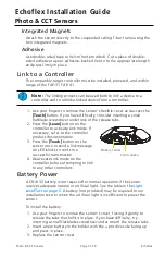
1. Use your fingers to remove the sensor's flexible cover and access the
[Teach]
button. If you have difficulty, consider inserting a small
flatblade screwdriver under one of the release tabs.
Teach button
Battery holder
2. Press the
[Learn]
button on the
controller to activate Link mode. If
necessary, refer to the controller
product documentation.
3. Press the
[Teach]
button on the
sensor once to send a link message.
An LED blinks to confirm a
successful transmission.
4. Deactivate Link mode on the
controller before attempting to link
to any other controllers.
Battery Power
A CR1632 battery is not required for normal operation if the sensor
receives adequate natural or artificial light. See the table in the
. A battery (not provided) may be required to run
installation tests or when the artificial light is insufficient to power the
sensor.
To install the battery:
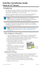
1. Use your fingers to remove the sensor's cover, flexing it gently to
release the tabs that hold it in place. If you have difficulty, try
inserting a small flatblade screwdriver under one of the release tabs.
2. Insert a new battery in the holder with the + positive side facing up
and press in place.
3. Replace the sensor cover.
Photo & CCT Sensors
Page 3 of 8
Echoflex


