background image

3

Installation Guide

tel - 1-800-477-2267 (East Coast) - 1-888-883-2790 (West Coast)

email - support@aampglobal.com (US)

email - technical.eu@aampglobal.com (Europe)

Fitting Instructions

SSM-RBP / SSM-DIS 

Parking Sensor System  
with Buzzer or Display 

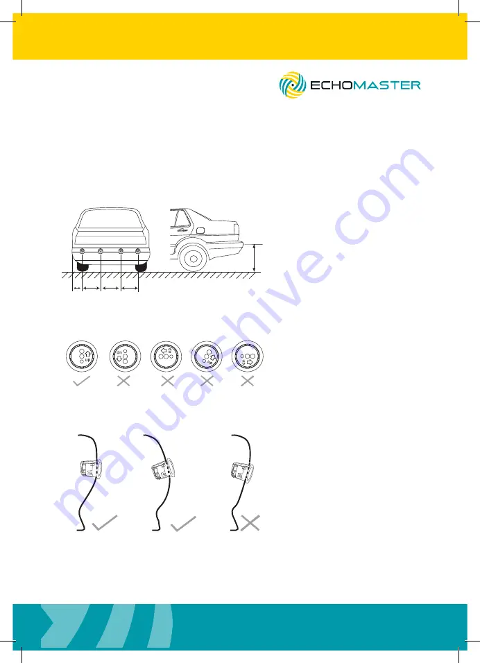
The sensors should ideally be equally spaced along the bumper.  For best results we 
recommend that the outer sensors are spaced between 8-13cm from the edge of the 
bumper.  

Sensor Spacing

A B

C D

8-13cm 30-40cm 30-40cm 30-40cm

55-80cm

Sensor Height

The sensors should then be 
spaced between 30-40cm 
from each other as shown in 
the diagram.

Sensor Orientation

Please note the orientation arrow 
on the sensors as shown.  
This should be pointing up for 
the sensors to work correctly.

Please also be aware that the 
sensors should be mounted 
parallel to the ground or slightly 
upwards facing. They should 
under no circumstances be 
angled downwards.

Parallel or Upwards Angle Mounting

Summary of Contents for SSM-DIS

Page 1: ...User Manual Parking Sensor System with Buzzer or Display SSM RBP SSM DIS ...

Page 2: ...s follow recommended safe driving guidelines from your local State and County Department of Motor Vehicles regarding parking procedures To help prevent accidents always use caution when parking looking visually to ensure your path is clear Keep speeds under three miles per hour The owner shall not be entitled to recover from the Company its successors or assignees incidental and consequential dama...

Page 3: ...e spaced between 8 13cm from the edge of the bumper Sensor Spacing A B C D 8 13cm 30 40cm 30 40cm 30 40cm 55 80cm Sensor Height The sensors should then be spaced between 30 40cm from each other as shown in the diagram Sensor Orientation Please note the orientation arrow on the sensors as shown This should be pointing up for the sensors to work correctly Please also be aware that the sensors should...

Page 4: ...nect to 12V switched reverse wire Blue Not connected in rear mode In front mode connect to the supplied switch and connect the other side of the switch to 12V IGN White Not connected in rear mode In front mode connect this wire to the vehicle analog speed pulse wire this can often be found behind the radio or the instrument cluster Grey Only used when combining 2 kits into a complete front and rea...

Page 5: ...n Using footbrake with buzzer Red GND Black Not Used Blue Not Used White Not Used Grey Foot Brake Yellow Buzzer SW1 ON OFF SW2 Rear Operation No Turn Off Delay Reverse Red GND Black Not Used Blue Not Used White Not Used Grey Reverse Yellow Buzzer SW1 ON OFF SW2 Rear Operation No Turn Off Delay IGN Red GND Black Not Used Blue Not Used White Not Used Grey Reverse Yellow Buzzer used only in rear inst...

Page 6: ... Used Red Black Blue White Yellow Low speed 12V output Black SW1 ON OFF SW2 Rear Operation With Display IGN GND Not Used Override Switch Reverse Not Used Red Black Blue White Yellow Not Used Not Used Grey SW1 ON OFF SW2 Front Rear Operation IGN Rear kit Front kit Red GND Black Not Used Blue Not Used Not Used White Reverse IGN GND IGN Override Switch Speed Not Used Yellow Red Black Blue White Yello...

Page 7: ...tinuous tone being heard 20 cm earlier than usual to account for the extra length of the protrusion u Up ON Distance adjustment on uDown OFF No distance adjustment PLEASE NOTE Dip switch 2 has no function when the kit is placed in front mode Speed Sensor Setting When in front mode the speed sensor requires calibration before it can work correctly To accomplish this drive the vehicle at the desired...

Page 8: ...hes it means that sensor is faulty It will also signify whether this is front or rear by use of the arrows on the display Please see the drawing below for fault detection indicators Sensor A Fault Front Fault Rear Fault Sensor B Fault Sensor C Fault Sensor D Fault Rear Application For rear applications SSM DIS or SSM RBP can be used When reverse is engaged the system will beep once to notify the d...

Page 9: ...on the display The top arrow signifies a front obstruction and the lower one a rear If an obstruction is present at both the front and rear of the vehicle then the display will alternate between the two If no movement is detected for 2 seconds then the audible alert will be muted but the visual alert will remain active If movement is then detected again audible and visual alerts will resume To tur...

Page 10: ...SSM DIS Operating Voltage Range 10 5 16V DC Rated Voltage 12 24V DC Rated Current 30 280mA Operating Temperature 30 70C Waterproof Grade Sensors Module Sensors IP67 Module IP40 Detection Range Front 0 2 0 7m Rear 0 2 1 5m Ultrasonic Frequency 40KHz Hole Saw Hole Saw included in SEN XX Specification SSM RBP SSM DIS Parking Sensor System with Buzzer or Display ...

Page 11: ...stallation Guide tel 1 800 477 2267 East Coast 1 888 883 2790 West Coast email support aampglobal com US email technical eu aampglobal com Europe SSM RBP SSM DIS Parking Sensor System with Buzzer or Display ...

Page 12: ...stallation Guide tel 1 800 477 2267 East Coast 1 888 883 2790 West Coast email support aampglobal com US email technical eu aampglobal com Europe SSM RBP SSM DIS Parking Sensor System with Buzzer or Display ...

Page 13: ...stallation Guide tel 1 800 477 2267 East Coast 1 888 883 2790 West Coast email support aampglobal com US email technical eu aampglobal com Europe SSM RBP SSM DIS Parking Sensor System with Buzzer or Display ...

Page 14: ... Coast 1 888 883 2790 West Coast email technical eu aampglobal com Europe 15500 Lightwave Drive Suite 202 Clearwater Florida 33760 Woolmer Way Bordon Hampshire United Kingdom EchoMaster is a Power Brand of AAMP Global EchoMaster com SSM RBP SSM DIS_v2060318 ...

Reviews: