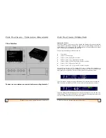
background image

32


FLS 

Platinum


Instruction Manual 


We hope you enjoy using your 

EchoPilot FLS Platinum


WE ARE ALWAYS PLEASED TO TALK TO OUR CUSTOMERS.


Information  in  this  document  is  subject  to  change  without  notice.  No  part  of  this  document  may  be 

reproduced or transmitted in any form or by any means, electronic or mechanical, for any purpose, without 

the express written permission of EchoPilot Marine Electronics Ltd.


Copyright © 2005 by EchoPilot Marine Eletronics Ltd. All rights reserved.


Protected by USA Patent  5530680 and European (UK) Patent 0624253


Author: Paul Beeston 


Last Updated: 29.11.2017 (Johnny Christensen)


For up to date information and advice, please telephone, browse our Website, or send 

us an E

-

Mail.


e

-

mail:  sales@echopilot.com


website: www.echopilot.com


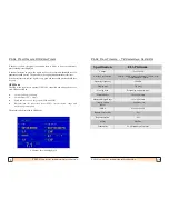
NMEA 0183 (ver 2.0) Accepted Input Sentences


Formatter


Description


BWC


Bearing and Distance to Waypoint


BWR


Bearing and Distance to Waypoint, Rhumb Line


DBT


Depth Below Transducer


DPT


Depth


GGA


Global Positioning System Fix Data


GLL


Geographic Position, Latitude/Longitude


RMA


Recommended Minimum Specific Loran

-

C Data


RMB


Recommended Minimum Navigation Information


RMC


Recommended Minimum Specific GPS/TRANSIT Data


VHW


Water Speed and Heading


VLW


Distance Travelled through the Water


VTG


Track Made Good and Ground Speed


ZDA


Time and Date


NMEA 0183 (ver 2.0) Output Sentences


All sentences accepted by the FLS Platinum are also output. 


Depth & log sentence information output from the unit will depend on the depth and log source selected. If 

the depth & log sources are set to local, then the depth and log sentences output will be the internally 

calculated depth/log data.


Sentences are output at 2 second intervals.


1


FLS Platinum Instruction Manual  

ECHOPILOT MARINE ELECTRONICS LTD


1 Endeavour Park, Crow Arch Lane, Ringwood,


Hampshire,  United Kingdom.  BH24  1SF.  


Telephone: 01425 476211/2


Fax: 01425 474300


E

-

Mail: info@echopilot.com


Webpage: www.echopilot.com


Professional 


Forward Looking Sonar 

DANIAMANT ELECTRONICS A/S


Industrivej 24C, 


3550 Slangerup, Denmark


Telephone: 0045 47373800


E

-

Mail: sales@echopilot.com /


service@echopilot.com


Webpage: www.echopilot.com


FLS Platinum  

FORWARD LOOKING SONAR 

INSTRUCTIONS 

Summary of Contents for fls platinum

Page 1: ... Data GLL Geographic Position Latitude Longitude RMA Recommended Minimum Specific Loran C Data RMB Recommended Minimum Navigation Information RMC Recommended Minimum Specific GPS TRANSIT Data VHW Water Speed and Heading VLW Distance Travelled through the Water VTG Track Made Good and Ground Speed ZDA Time and Date NMEA 0183 ver 2 0 Output Sentences All sentences accepted by the FLS Platinum are al...

Page 2: ...pleasure and safety from your equipment so please take the time to read the instructions Please observe the following warnings Please do not cut the transducer cables they are fine multi core cable matched to the transducer Please do not remove the transducer plug from its cable if a hole is too small make the hole bigger Any join in the cable will reduce sensitivity performance Disclaimer Echopil...

Page 3: ...rview 5 Operating Modes 5 Changing the Unit Settings 11 Operating a Repeater Unit 15 How FLS Technology Works 16 Some Guidance on Use 17 Installation Instructions 18 Transducer Installation 18 Wiring Diagrams 21 Fitting the Transmitter Box 22 Applying Power 23 Maintenance 23 Fault Finding 24 Technical Specification 25 Technical Drawings 26 Contents ...

Page 4: ...onar display The sonar data displayed on the screen will depend on the sea bed below the transducer The unit will always switch on in Auto Range mode which means that if a good seabed signal is received a suitable range will be chosen for the current depth Pressing the up or down arrows will turn off auto mode and the user will now have control of the range with the up and down arrows Power Key Me...

Page 5: ... screen See FLS Mode section for more information When in Test Mode cycles through three test screens that will aid in testing the unit and provide diagnostic information See Test Mode section for more information The page key has no effect in GPS Mode See GPS Mode section for more information Operating Modes FLS Mode FLS Mode is the sonar operating mode that displays the sonar image of the seabed...

Page 6: ...l connection and a red cross indicates that the transmitter box is not properly connected no power to the transmitter box and or not connected to the display unit The status indicator also shows whether Auto Range is on or off History Display The FLS Platinum displays a 15 second history to the left of the vertical line 0m line on the sonar display The history plot is based on the digital depth re...

Page 7: ...displays enabled Depth Speed Log log displays enabled Depth Speed Echo Strength log displays enabled Depth GPS GPS displays enabled Depth Speed GPS log and GPS displays enabled Speed and log info can only be displayed if either a paddle wheel transducer is connected to the display unit speed through the water or a GPS is connected to the unit speed over the ground The source of the speed is select...

Page 8: ... Speed and course over the ground COG and SOG Waypoint info ID cross track error XTE steer direction range and true bearing to waypont The depth is also displayed in GPS Mode GPS Mode data including depth FLS Platinum Operating 25 FLS Platinum Instruction Manual FLS Platinum Installati Specification FLS Platinum Voltage 12v or 24v DC Current Consumption Display 700mA with max brightnes 300 mA min ...

Page 9: ...S Platinum Fault Finding 9 FLS Platinum Instruction Manual Test Mode This mode allows the user to obtain diagnostic data about the unit should a fault occur with the display transmitter box or transducer The page key scrolls between 3 test pages A Scan and Angle Graphs These graphs display the sonar signal strength and associated calculated angles over a 30m range If the depth is greater than 30m ...

Page 10: ...l FLS Platinum Installation Interference Other depth sounders especially those that operate at 200 kHz must be wired so they can be switched off if interference occurs This may appear as submarine like echoes coupled with a reduction in sensitivity Applying Power When power is applied to to FLS Platinum system 2 LEDs on the transmitter box show the status of power and the communications link to th...

Page 11: ...n when the display is switched off Therefore power should be removed via the switch when not in use An optional paddle wheel for water speed may also be attached to the 8 pin cable on the master unit if required Please refer to the wiring diagrams on page 21 for further details on connecting up the video interface and transmitter box 11 FLS Platinum Instruction Manual FLS Platinum Operating NMEA V...

Page 12: ...t of noise that will show A lower value will filter more of the signal and reduce the amount of noise but will give a weaker echo on the display Max is recommended for most uses Noise Filter This setting allows the user to reduce the amount of clutter on the sonar display The filter lever sets the number of times an echo must occur within a similar location before it is displayed Setting the filte...

Page 13: ...lour The echoes displayed in FLS Mode can be either strength encoded or mono Strength encoded echoes use colours to show strength variations between echoes with red being the strongest echo then green then yellow then light blue for the weakest echoes Mono colour selects a single suitable colour that all echoes will be displayed as depending on the colour mode chosen Boat Length Allows the user to...

Page 14: ...as it would a transmitter box It should be noted that changing range on a repeater unit will be independent of the master unit so they may both be on different ranges unless both units are set to Auto Range However it is the range selected on the master unit that will dictate 19 FLS Platinum Instruction Manual FLS Platinum Installation Sailing Boats On a fin keeled boat alongside the keel and perh...

Page 15: ...r the transducer looks down as well as ahead so when manoeuvring in shallow waters you may wish to see there is water for the propellers and rudders Sonar cannot see around corners so before installing stand under the boat with your head near the proposed position and check that you can see from your toes up to above the horizontal ahead If the boat has a full or deep forefoot and is shallow aft a...

Page 16: ...ved and processed by the FLS Unlike older FLS models the depth can now be calculated regardless of the selected range and therefore can be useful for the user in selecting the correct range The depth relies on a good quality sonar signal and care should be taken in poor sonar conditions e g turbulence from passing boats or another sounder running at the same frequency causing excessive noise Care ...

Reviews: