


10
FLS
Platinum
Instruction Manual
FLS Platinum Operating
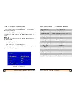
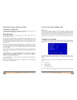
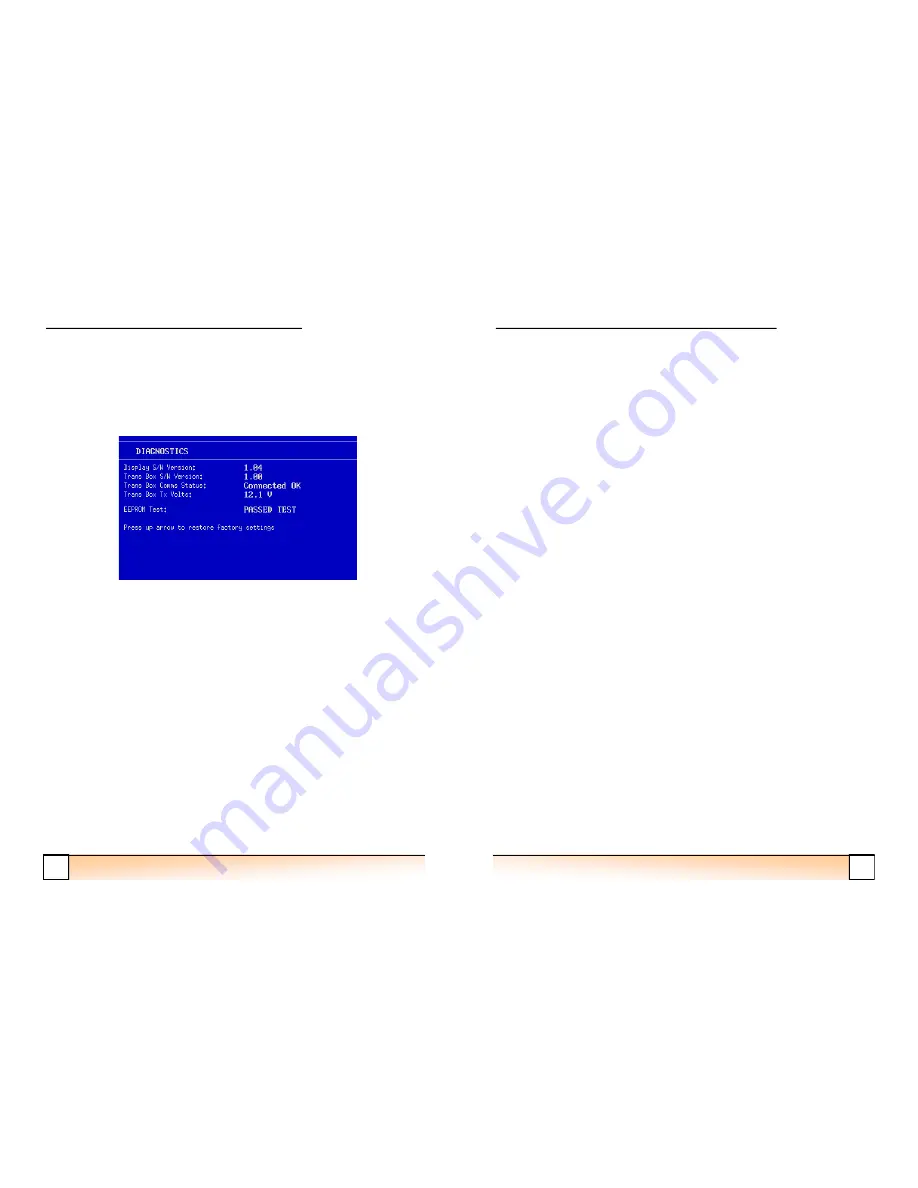
Diagnostics
This screen displays some diagnostic information about the unit. It shows the
software version of both the transmitter box and the display, the status of the
communications link with the transmitter box, the transmitter dc voltage supply and
also tests the settings memory on the display (EEPROM).
Diagnosic Data
‘
Trans Box Comms Status
’
should read
‘
Connected OK
’.
Any other messages mean
an error has occured on the communications link with the transmitter box. If this is
the case, the user should ensure that the transmitter box has power and the data link
cable is connected securely at both ends (transmtter box and display).
‘
Trans Box Tx Volts
’
should read approximately 12 Volts. If the transmitter box
supply voltage is at exactly 12 Volts, then the Tx Volts should be about 9
-
10 Volts.
This will result in slight reduced peformance but should still perform well. If 14 Volts
or more are supplied to the transmitter box, maximum transmit power will be
achieved.
Factory settings can be restored by pressing the up arrow key on this page.
23
FLS Platinum Instruction Manual
FLS Platinum Installation
Interference
Other depth sounders especially those that operate at 200 kHz must be wired so
they can be switched off
if interference occurs. (This may appear as
‘
submarine
’
like echoes coupled with a reduction in sensitivity).
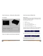
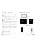
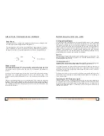
Applying Power
When power is applied to to FLS Platinum system, 2 LEDs on the transmitter box
show the status of power and the communications link to the display unit.
The left LED shows power is reaching the box and this should be lit as soon as power
is applied to the transmitter box.
The right LED should also light upon applying power to the transmitter box. If
successful communication with the display is made, the LED will flash to show that
the display unit is in FLS Mode and that the transmitter box is receiving transmission
requests from the display. If this LED is not flashing, check that the display has
power connected and is switched on
-
and that the 12m data cable is connected
properly at both ends.
Maintenance
Keep transducer
‘
O
’
rings and locking ring thread well greased with a silicone grease.
Protect plugs and cables from chafe. Clean the transducer face regularly and check
for barnacles etc. With care, this may be done afloat. If you have never done this
before, phone us first! You may anti
-
foul the transducer. Avoid long term exposure
of the LCD to direct sunlight.


