

22
FLS
Platinum
Instruction Manual
FLS Platinum Installation
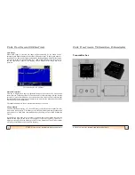
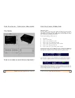
Fitting the Transmitter box
The transmitter box should ideally be mounted on a vertical surface, within reach of the
transducer cable (2m) and protected from excessive moisture.
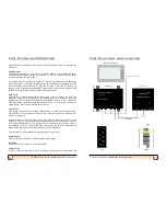
Plugs and sockets
The 2m transducer cable (8 pin plug) connects to the right hand socket of the
transmitter box marked
TX
.
The pre
-
wired (5 pin) 12m cable is connected from the left hand socket on the
transmitter box marked
OUT
to the right hand socket (viewing display from the rear)
marked
IN
on the display unit. An optional repeater can be connected with a second
12m cable connected to the
OUT
connector on the master unit and the
IN
connector on
the repeater unit.
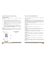
The short cable for the power supply and NMEA (in and out) plugs into the centre (8
pin) socket on both the master unit and the optional repeater unit. If NMEA is required
on the Repeater unit, a cable for carrying NMEA data from the master to the Repeater
unit is also required.
Power is also required for the lower transmitter box and should be supplied through an
on/off switch (not supplied) mounted conveniently near the display. Power may be 12
or 24 Volts.
The transmitter box draws approximately 50mA of current when power is
applied, even when the display is switched off. Therefore, power should be
removed via the switch when not in use
.
An optional paddle wheel for water speed may also be attached to the 8 pin cable on the
master unit if required.
Please refer to the wiring diagrams on page 21 for further details on connecting up the
video interface and transmitter box.
11
FLS Platinum Instruction Manual
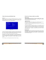
FLS Platinum Operating
NMEA Viewer
This page allows incoming data from a GPS or other NMEA compatible instrument
to be viewed to ensure that the NMEA connection is correct and that the appropriate
sentences are being received. 4 pages can be scrolled using the up arrow keys to view
all the sentence types that the unit can receive and whether any data is being received.
Each line under each sentence type is in field order as specified in NMEA 0183 ver
2.0.
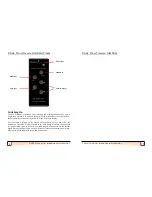
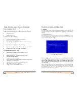
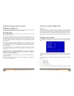
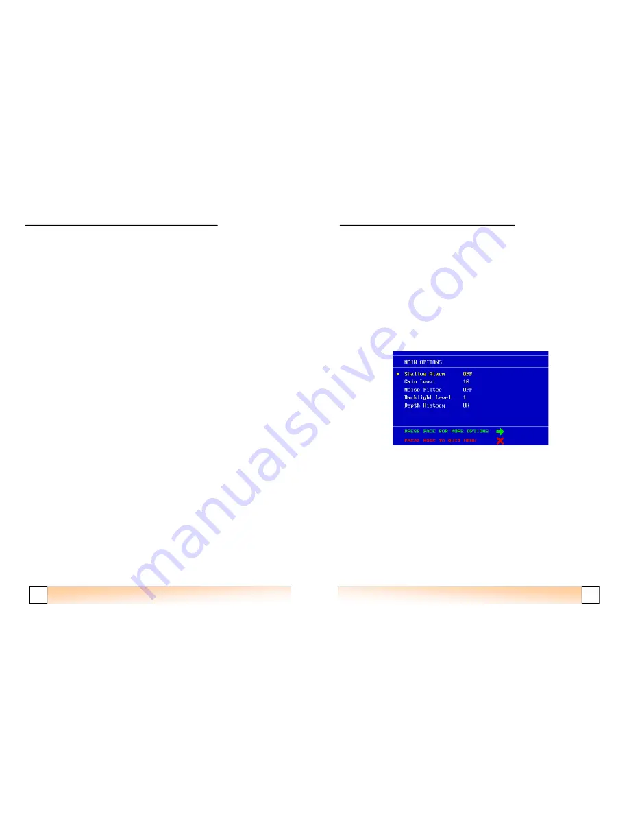
Changing the Unit Settings
A simple menu system allows the user to change the unit settings. Pressing the menu
key while in any of the display modes enters the menu, presenting the following
page:
-
The desired menu option is chosen using the menu key. When the arrow cursor is
alongside the appropriate option, pressing the up or down
arrow keys changes the
setting.
Pressing the page key presents the user with another set of options. There are 4 menu
pages:
•
Main Options
•
Display Options1
•
Display Options 2
•
Depth and Log Options
The unit will return to the sonar display after 10 seconds if no buttons are pressed


