

12
FLS
Platinum
Instruction Manual
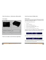
within that time. Alternatively, the user can return to the sonar display by pressing the
mode key.
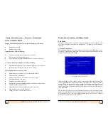
Shallow Alarm
The Shallow Alarm can be set to Off or 1m to 20m. When a certain number of echoes
occur above this setting, an alarm will sound (1 second on, 1 second off). The alarm
setting is retained after power down.
The shallow alarm is provided as a guide to warn the user that echoes are appearing
above the set level. It should be noted that in some conditions (particularly in noisy
sonar conditions) the alarm may be triggered by echoes from the sea surface (in
choppy water), or turbulence generated by other vessels. As experience is gained with
the FLS, the user should be able to identify this kind of noise.
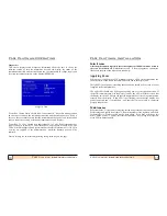
Gain Level
The gain level controls the amount of sonar signal level accepted by the FLS. The
higher the value, the more signal will be accepted and give a stronger echo on the
display
-
but will also increase the amount of noise that will show. A lower value will
filter more of the signal and reduce the amount of noise
-
but will give a weaker echo
on the display. Max is recommended for most uses.
Noise Filter
This setting allows the user to reduce the amount of
‘
clutter
’
on the sonar display.
The filter lever sets the number of times an echo must occur within a similar location
before it is displayed.
Setting the filter to off means that echoes only need to appear once in order to be
displayed. This gives much more detail and responsiveness on the display but will
also increase the amount of noise displayed (from air bubbles for example) which is
more random. The low, medium and high settings increase the filter gradually and
hence reduce the responsiveness and number of echoes displayed.
The off setting is recommended as a starting point for most users.
Depth History
Allows the user to switch on or off the depth history display.
Key Bleep
Allows the user to switch on or off the key bleep
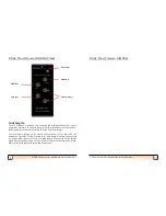
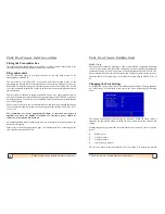
Colour Mode
6 colour modes are provided to allow a choice of colour sets to be selected by the
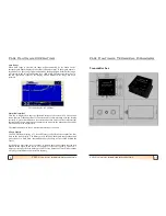
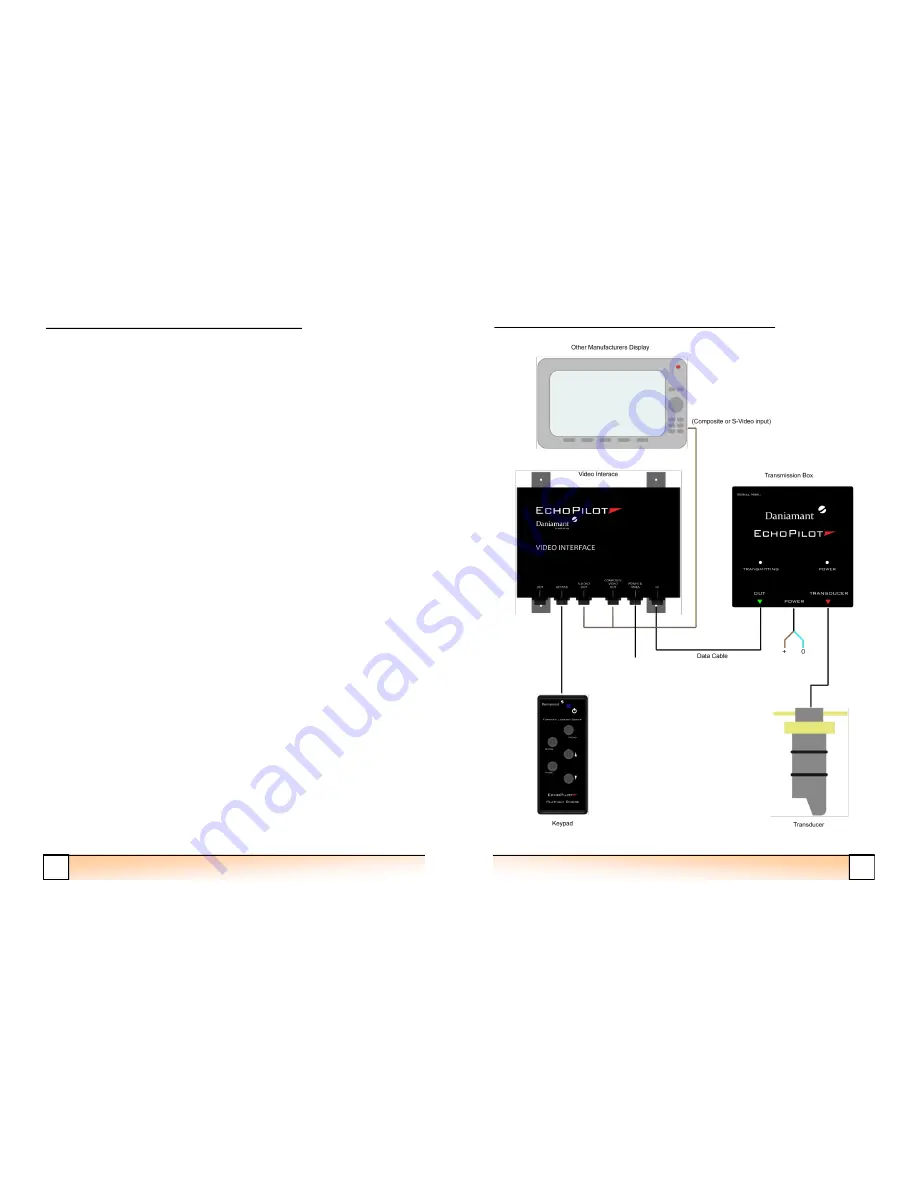
FLS Platinum Operating
21
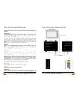
FLS Platinum Instruction Manual
FLS Platinum Installation


