

20
FLS
Platinum
Instruction Manual
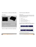
FLS Platinum Installation
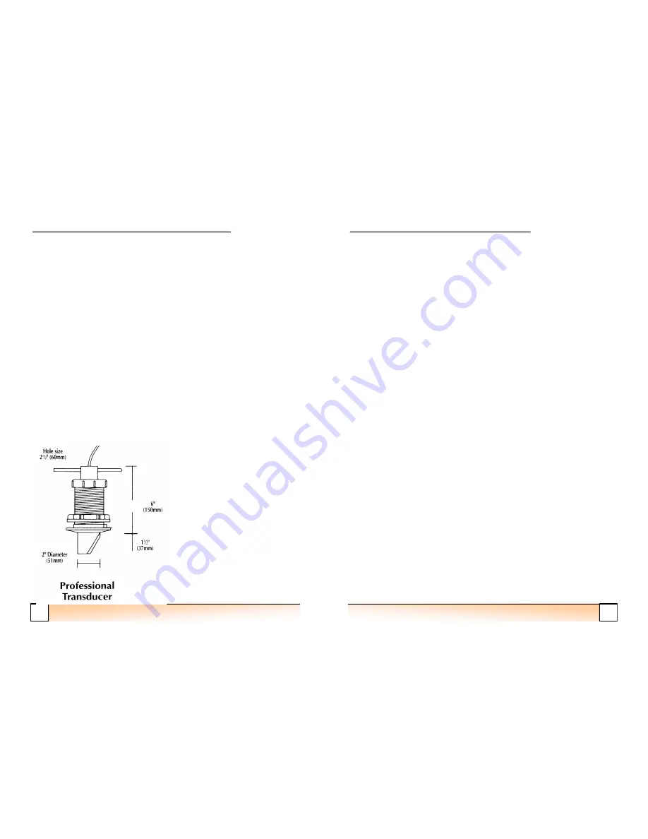
Fitting the Skin Fitting
A hole in the boat must be taken seriously!
-
If in doubt use an experienced
shipwright.
•
For the Log plastic skin fitting
-
cut a 45 mm (1
3
/
4
") diameter hole.
•
For the Professional bronze skin fitting
-
cut a hole 60 mm (2
1
/
2
") in diameter.
•
Fit the skin fitting with reinforcing pads if needed or wedges if required to
ensure the transducer is as near to vertical as possible (fore/aft AND port/
starboard).
•
Use plenty of underwater sealant, but take care to clean off the thread
thoroughly afterwards.
•
Secure with the nut on the inside. Do not use excessive force on the nut.
•
If the vessel will be floated
before
the transducer is fitted, the blanking cap
provided must be fitted to seal the skin fitting. (N.B. for our American
customers, for
“
skin fitting
”
read
“
thru
-
hull fitting
”).
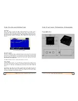
Safety
The transducer provided is designed to shear off (in the event of a severe impact),
flush with the hull, leaving the solid epoxy filled portion in the through hull fitting,
and thus poses no risk of water ingress.
Maximum hull thickness:
75 mm (3")
13
FLS Platinum Instruction Manual
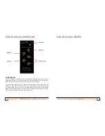
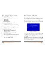
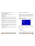
FLS Platinum Operating
user. 3 sets are for daytime use (light background colours) and 3 for night
-
time use
(dark background colours).
Echoes Colour
The echoes displayed in FLS Mode can be either strength encoded or
‘
mono
’.
Strength encoded echoes use colours to show strength variations between echoes
-
with red being the strongest echo, then green, then yellow, then light blue for the
weakest echoes. Mono colour selects a single suitable colour that all echoes will be
displayed as, depending on the colour mode chosen.
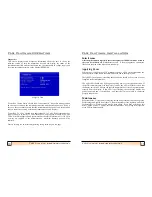
Boat Length
Allows the user to set the displayed boat length to match their own boat (up to a
maximum of 20m).
Boat Type
3 boat types are available to the user: 2 motor boats and 1 sailing boat.
Bow Offset
This is the distance from the boat
’
s bow to the transducer position and allows the user
to obtain a more realistic picture of the seabed with respect to the vessel.
GPS Displays
Allows the GPS displays to be switched off in the information wndow in FLS Mode.
This reduces the number of combinations that can be cycled through.
Log Displays
Allows the speed and log displays to be switched off in the information wndow in
FLS Mode. This reduces the number of combinations that can be cycled through.
UTC Offset
Allows an offset to be applied to the received UTC time so that the local time can be
displayed in GPS mode.
Language
Allows one of the currently available languages to be selected for unit operation.
Depth Source
Allows either local (FLS transducer) or NMEA to be chosen as the depth source. If
NMEA is selected, the depth data will be searched for automatically in the incoming
NMEA data.


