


14
FLS
Platinum
Instruction Manual
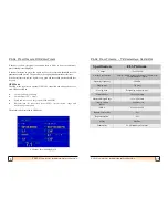
FLS Platinum Operating
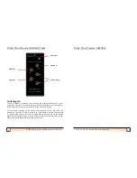
Depth Units
Units can be set to Metres or Feet.
Depth Offset
The Depth Offset can be set from
-
3.0m to +3.0m. If the offset is positive, the set
offset will be added to the calculated depth below transducer to give depth below
the surface If the offset is negative, the set offset will be subtracted from the
calculated depth below transducer to give depth below the keel.
This offset only applies to the digital depth readout in the bottom left hand corner of
the display and NOT the graphical seabed picture.
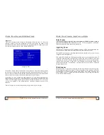
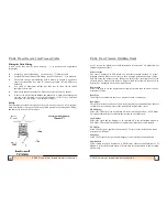
Log Reset
Pressing the up or down keys will reset the current log trip distance.
Log Source
Allows either local (paddle wheel) or NMEA to be chosen as the log source. If
NMEA is selected, the speed/log data will be searched for automatically in the
incoming NMEA data. NMEA STW (speed through water) searches for speed
through water data in the approiate sentences. NMEA SOG (speed over ground)
searches for speed over ground data in the appropriate sentences.
Log Units
Units can be set to either Knots, KPH or MPH.
Log Cal.
The optional Log transducer supplied with the FLS Platinum produces pulses which
are proportional to the speed of the boat. It is these pulses which give you your
speed. However, due to boat hull design, the water flow at the sensor can be faster
or slower than the actual water speed of the boat. The FLS Platinum allows for the
log speed, trip and total trip displays to show between 20%
-
250% of the actual
log sensor reading.
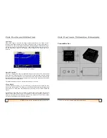
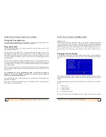
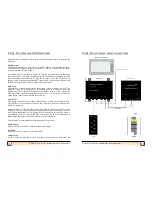
Operating a Repeater Unit
A repeater display unit is identical to a master display unit and operates in exactly
the same way. The repeater unit will treat the master unit as a transmitter box and
will communicate with it in the same way as it would a transmitter box.
It should be noted that changing range on a repeater unit will be independent of the
master unit so they may both be on different ranges (unless both units are set to
Auto Range). However, it is the range selected on the master unit that will dictate
19
FLS Platinum Instruction Manual
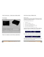
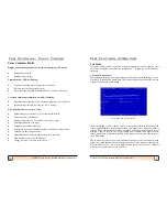
FLS Platinum Installation
Sailing Boats
On a fin keeled boat, alongside the keel and perhaps 60cm or 2 feet out
-
because the beam is approximately 15 degrees overall in the horizontal plane, is
often a well protected position. But this is unsuitable for a winged keel or large
bulb as the signal from the transducer could impinge on these. Just forward of
the keel is an alternative, but take care when hoisting the boat in a sling!
Do not fit the transducer too far forward where it will come out of the water as
the vessel pitches. The transducer looks ahead as well as down and you need to
see what is under your boat as well as what is ahead. When manoeuvring in
shallows you will wish to know what is under the keel or rudder.
A long keel boat is harder, choose the position with the minimum angle of
deadrise (ie the flattest area) and fit the transducer with a pair of wedge shaped
chocks if necessary, so that it is as near to vertical as possible with the boat
upright. On boats with slack bilges it maybe necessary to fit the professional
transducer, even on a small vessel, because its skin fitting has more useable
thread. If the transducer leans forward the seabed will appear to slope up and if
it leans aft there maybe surface clutter.`
Choose a position with good access so that the transducer can be withdrawn for
cleaning if necessary.
Remember that sonar cannot see around corners, so stand under the boat with
your head near the proposed position. You must be able to see from your toes up
to above the horizontal ahead. If the boat has a full or deep forefoot obstructing
the view a more forward position maybe called for.


