


18
FLS
Platinum
Instruction Manual
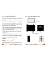
Transducer Installation
The choice of transducer position will have a major effect on final performance so
please consider carefully all factors and if in any doubt, telephone the factory.
Motor Boats
On a small planing hull fit the transducer as far aft as reasonably possible. On a stern
drive boat (inboard or outboard) typically fit just in front of the engine(s). On a shaft
driven boat (not V drive) forward of the shaft log or stern gland, but behind the
gearbox. On larger vessels fit further forward to increase effective range.
Keep inboard of the lower spray rail if possible.
Do not fit downstream of any other through hull fittings (for example intakes, log,
toilet sea cocks etc) and choose a location with good access for withdrawing the
transducer for cleaning.
The transducer should ideally be vertical in the fore and aft plane at running trim. If it
leans forward the seabed will appear to slope up, and if it rakes aft then a degree of
surface clutter may show. Some heel to port or starboard is acceptable, to a maximum
of 5 degrees.
Avoid the temptation to fit the transducer too far forward as it may then be out of
solid water when at speed or pitching. Also remember the transducer looks down as
well as ahead, so when manoeuvring in shallow waters you may wish to see there is
water for the propellers and rudders.
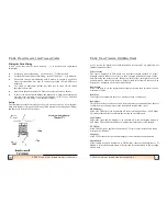
Sonar cannot see around corners so before installing stand under the boat with your
head near the proposed position and check that you can see from your toes up to
above the horizontal ahead. If the boat has a full or deep forefoot and is shallow aft a
forward mounted transducer maybe necessary.
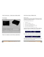
FLS Platinum Installation
15
FLS Platinum Instruction Manual
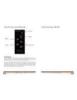
FLS Platinum Operating
the transmission pulse length set by the transmitter box and also the A
-
Scan channel
displayed in Test Mode.
A master unit and a repeater unit will be interchangable so that if a fault should occur
in the master unit for any reason, the repeater may be used as a direct replacement.
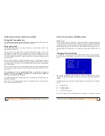
Demo Mode
To enter demo mode, ensure the unit is switched off first. Then press and hold the
power button until a second beep is heard. The sonar display should appear with one
of the 3 demo seabeds.
‘
Demo Mode
’
will appear in the Status Indicator box in the
top right hand corner of the display.
Pressing the up or down arrow key will cycle the demo display around 3 demo
screens. The menu is operational but some settings will have no effect in demo mode.
In particular, shallow alarm (although the alarm bell will be shown), gain level, noise
filter, colour mode and echoes colour will not work in demo mode.


