

8
FLS
Platinum
Instruction Manual
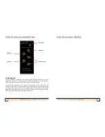
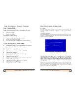
If the bar is yellow, the signal is weak and there is likely to be no (or extremely
poor) seabed picture displayed.
If the bar increases to green, the signal is above the acceptable threshold level to
generate a seabed picture. The picture may be slightly disappointing at this level.
If the bar increases to red, the signal is very good and the seabed picture should also
be good.
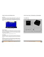
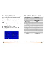
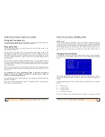
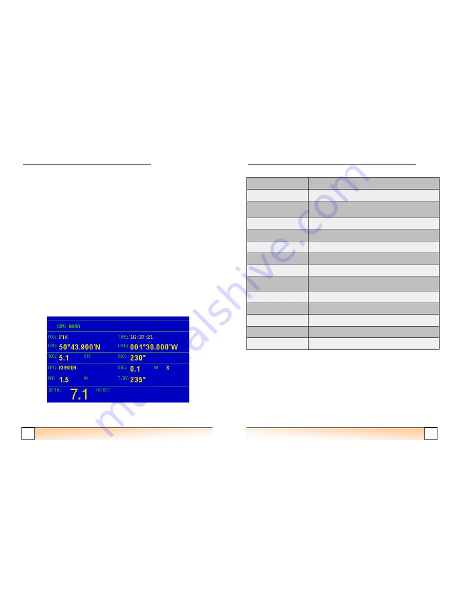
GPS Mode
The GPS mode requires an external GPS to be connected and allows the user to
view GPS data such as:
-
•
Current position (Lat/Long)
•
Current time (UTC + offset)
•
Speed and course over the ground (COG and SOG)
•
Waypoint info (ID, cross track error (XTE) + steer direction, range and
true bearing to waypont)
The depth is also displayed in GPS Mode.
GPS Mode data including depth
FLS Platinum Operating
25
FLS Platinum Instruction Manual
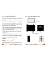
FLS Platinum Installati
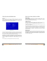
Specification
FLS Platinum
Voltage
12v or 24v DC
Current Consumption
Display
-
700mA with max brightnes (300 mA min)
Transmitter Box
-
50mA
Operating frequency
200 kHz
Display type
3rd party
Viewing Area
Depending on display type
Forward Range
20 to 200 metres
Maximum Depth Range
10 to 100 metres
Display Update
Rates
1
-
2 updates / sec
NMEA
0183 Version 2.0
Built
-
in Test Facility
Yes
Repeater Option
Yes
Alarm
Shallow
Transducers
FLS Platinum professional
FLS Platinum - Technical Specs


