Chapter 3
•
Using the LCD keypad
H55651
Revision E
25
Under battery power:
•
Three segments: 75% to full
•
Two segments: 50% to 74%
•
One segment: 25% to 49%
•
Zero segments: 10% to 24%
•
Zero segments, flashing: 0% to 9%
If the icon is off, no battery has been detected or the AC/DC converter is not connected.
Under external power (UT “on” or “off”)
Icon will flash zero, then one, then two and then three segments, one second each, while charging to
display level of charge state while charging.
Three segments steady when fully charged and the LCD will show “Charged.”
No battery present
Blank battery icon
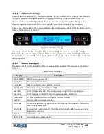
3.5.2
Power icon
The power icon displays the state of the
external power input
.
•
On if external power is connected.
•
Off if external power is disconnected.
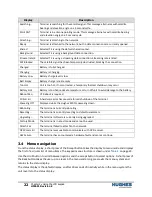
3.5.3
GPS icon
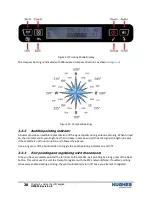
The GPS icon indicates the state of the GPS information in the terminal.
The icon
flashes
after power up until a fresh GPS fix is obtained.
The icon is
on steady
when the terminal has a new fix.
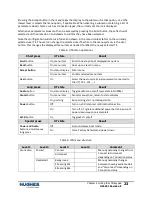
3.5.4
Satellite icons
The satellite icons, located next to the GPS icon, indicate the
status of the GPS receiver
in the terminal and the
number of visible satellites
.
The icons are
off
when the
GPS receiver is off
.
The icons are
active
when the
GPS receiver is on
, either flashing or steady state. The number of icons in
steady state indicates the number of GPS satellites acquired and tracked . You will need all three on solid
to acquire a new GPS fix. Note that once an adequate GPS fix is obtained, both the GPS receiver and all
of the satellite icons are turned off and the word “GPS” should go on steady.
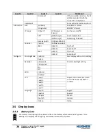
3.5.5
Wireless LAN icon
The wireless LAN icon displays the state of the Wi-Fi feature.
•
Off if Wi-Fi operation is turned off.
•
On if Wi-Fi is on.
3.5.6
Wireless LAN lock icon
The lock icon displays the state of encryption for the Wi-Fi feature. It is displayed only if Wi-Fi is
enabled and Wi-Fi encryption is turned on.
Summary of Contents for Hughes 4200
Page 1: ...Hughes 4200 User Guide H55651 Revision E July 09 2020 ...
Page 28: ...28 Chapter 3 Using the LCD keypad H55651 Revision E ...
Page 48: ...48 Chapter 4 Using the Web UI H55651 Revision E Figure 32 Modem Diagnostic page ...
Page 50: ...50 Chapter 5 Troubleshooting H55651 Revision E ...
Page 52: ...52 Chapter 6 Technical specifications H55651 Revision E ...
Page 58: ...58 Acronyms H55651 Revision E ...


