Chapter 1 • Installation instructions
H66664 Revision C
17
1.7
Power and data cable
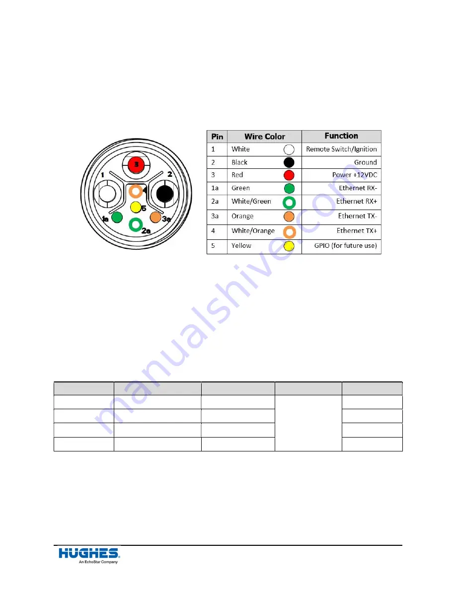
Every UNI 45XX power and data cable has provisions for the positive DC (red wire) and the ground (black
wire) lines along with a remote switch/ignition (white wire). The remote switch/ignition can be used for
vehicles to ensure power is only supplied to the terminal when the ignition switch is on. If the remote
switch/ignition wire is not used, a jumper wire must be connected between Pin 1 and Pin 3, or Pin 1
must be connected to the power source.
Figure 17: Power and data cable internal wires details
1.7.1
Custom connection (power and data cable: RJ45 wiring block)
If the user wants to connect one of the 45XX power and data cables to an RJ45, they must following the
procedures below:
1.
Strip the power and data cable to get to the internal wires shown in
Figure 17.
2.
Connect the RJ45 wiring block to the internal wires of the power and data cable using a
straight
‑
through connection. Follow the information in
Table 5
to achieve the correct
connection between the wires (45XX power and data cable) and the pinouts (RJ45).
Table 5: Pin-out table
Cable Pin
Cable Wire Color
Function
Connection
RJ45 Pinout
1a
Green
Ethernet RX-
Straight-through
6
2a
White/Green
Ethernet RX+
3
3a
Orange
Ethernet TX-
2
4
White/Orange
Ethernet TX+
2
3.
Strip and tin the remaining wires (power, ground, and remote switch wire ends) of the cable.
Note:
The yellow wire of the UNI power cable is for future use, so it can be ignored for now.
4.
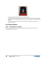
Use tie wraps for strain relief if necessary, see
Figure 18
for further details
5.
The remote switch/ignition can be used for vehicles to ensure power is only supplied to the
Terminal when the ignition switch is ON. If the remote switch/ignition wire is not used, then a
jumper wire must be connected between Pin 1 and Pin 3 or Pin 1 must be connected to the
power source.


