background image

 Contents 

H64159  Revision A 

iii 


Contents 

Understanding safety alert messages ..................................................................................... v


Messages concerning personal injury .................................................................................................... v


Messages concerning property damage ................................................................................................. v


Safety symbols ....................................................................................................................... vi


Introduction............................................................................................................................ 1


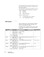
Overview ............................................................................................................................................. 1


9450 Variants ....................................................................................................................................... 2


About this User Guide .......................................................................................................................... 3


Package Contents ................................................................................................................................. 3


Minimum System Requirements for Laptop/PC .................................................................................... 3


Getting Started ..................................................................................................................................... 4


Installing your terminal ........................................................................................................................ 4


Terminal LED functionality .................................................................................................................. 4


Using the Hughes 9450 ........................................................................................................... 6


Auto start configuration ........................................................................................................................ 6


Power up and the connection to the Internet .......................................................................................... 7


Connecting the terminal to the computer ............................................................................................... 7


Connecting by Ethernet..................................................................................................................... 8


Power over Ethernet (POE) ............................................................................................................... 8


Connecting by WLAN ...................................................................................................................... 8


WLAN Security ............................................................................................................................ 9


Connecting by ISDN......................................................................................................................... 9


Connecting by RJ11 ........................................................................................................................ 10


Coverage Map .................................................................................................................................... 11


Operation in the MEAS cutout area ................................................................................................. 12


Operation in the Russian Federation ................................................................................................ 13


Using the Web UI ................................................................................................................. 14


Accessing the Web UI ........................................................................................................................ 14


Home page ......................................................................................................................................... 16


Connections ....................................................................................................................................... 19


Manage Connections ...................................................................................................................... 19


Automatic Contexts ........................................................................................................................ 20


Manage APNs ................................................................................................................................ 25


SMS ................................................................................................................................................... 27


Send/Receive .................................................................................................................................. 27


Saved Drafts ................................................................................................................................... 28


Summary of Contents for Hughes 9450 Series

Page 1: ...Hughes 9450 Series User Guide H64159 Revision A 27 December 2019...

Page 2: ...ffort to ensure the correctness and completeness of the material in this document Hughes Network Systems LLC shall not be liable for errors contained herein The information in this document is subject...

Page 3: ...l LED functionality 4 Using the Hughes 9450 6 Auto start configuration 6 Power up and the connection to the Internet 7 Connecting the terminal to the computer 7 Connecting by Ethernet 8 Power over Eth...

Page 4: ...M2M Page 48 Ping Configuration 48 Always On Context 48 Usage Page 50 Support Page 51 Smart Phone Web UI 54 Troubleshooting 56 PDP Context Activation Errors 56 Technology Overview 59 GPS 59 Obtaining...

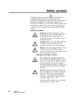
Page 5: ...ards that could result in personal injury or in some cases death as explained below Each of these signal words indicates the severity of the potential hazard DANGER indicates a potentially hazardous s...

Page 6: ...nd WARNING heading strictly follow the warning instructions to avoid personal injury Danger Electric shock hazard Where you see this alert symbol and DANGER heading strictly follow the warning instruc...

Page 7: ...rogress Observe all restrictions and follow any regulations or rules Areas with a potentially explosive environment are often but not always clearly marked Do not use the Terminal while at a petrol fi...

Page 8: ...emaker Refer to your pacemaker product literature for information on your particular device If you have any reason to suspect that interference is taking place turn off your Satellite Terminal immedia...

Page 9: ...power cable for vehicular installation Up to 492 Kbps data transmit and receive and 256 Kbps streaming IP data rate above 45 degrees look angle for C10 and 128Kbps streaming for C11 Four RJ 45 Power o...

Page 10: ...nt software release versions as shown below The upgrader protects against loading the wrong release 9450 Model Part Numbers Interfaces Software Release 9450 Kit 3500497 0001 C11 3500497 0002 C10 35004...

Page 11: ...When you unpack the Land Mobile Terminal Kit package you will find the following BGAN Land Mobile Tracking Antenna Kit Hughes 9450 BGAN Satellite Modem Kit Your Service Provider will supply you with a...

Page 12: ...tion Guide supplied with the terminal for either the C10 or C11 antenna You can also download the Installation guides and User manuals from our website at www bgan hughes com Please refer to the Insta...

Page 13: ...th 2 LEDs for each port with the following functions Green Red bicolor Green indicates Link active Red indicates a power over Ethernet PD device is connected and is being powered by the IDU When both...

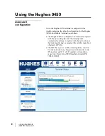
Page 14: ...is configured to automatically register with the network by default The terminal will automatically attempt to register with the network once the tracking antenna has acquired the satellite signal an...

Page 15: ...lly track the satellite signal and keep the antenna pointed towards the satellite During short outages e g while driving under a bridge etc the antenna will remain in the same position and will pick u...

Page 16: ...imum for 12 V installations and 61 6 W maximum for 24 V installations The ports can provide power to class 1 2 and 3 devices as long as the total power does not exceed the wattage based on the input v...

Page 17: ...ble to access your BGAN service If WEP or WPA is enabled you must provide other WLAN users with the security key in order for them to connect to the terminal In NAT mode you can go to the Manage Conne...

Page 18: ...3 1kHz at elevation angles of 45 degrees or greater and Class 10 terminals at elevation angles of 15 degrees and greater Check with your service provider for full details To dial prefix the internati...

Page 19: ...h 4 satellites as shown below The Hughes 9450 terminals will perform best in areas where the elevation angle is 20 degrees or higher Lower elevation angles increase the probability of signal outages c...

Page 20: ...cutout area I 4 MEAS has a cutout area in its coverage over China and nearby parts of Asia In this area I 4 Asia Pacific APAC must be used even if MEAS is closer For best operation in this area confi...

Page 21: ...c APAC even if one of these satellites is closer When operating in this region you can configure the UT to only use MEAS from the General Setup Page In areas within the Russian Federation but not cove...

Page 22: ...ccessing the Web UI The Hughes UT includes its own internal Web User Interface UI To access the web UI open your favorite Web Browser and type in the internal IP address of the UT e g http 192 168 128...

Page 23: ...Using the Web UI H64159 Revision A 15 If the 9450 has been converted to an M2M terminal the Home page icon will look like this e g 9450M Note streaming QoS is disabled in M2M mode...

Page 24: ...splays the current GPS position status If you have received a GPS fix and the Network GPS policy has been received and it allows the GPS position to be shown to the user it will display the Latitude L...

Page 25: ...field allows you to activate data connections for your TE You can activate a Standard connection or a Streaming connection For streaming connections use the drop down box to select the data rate for t...

Page 26: ...18 Using the Web UI H64159 Revision A The following figure shows how the UI looks if you activate a Standard connection Use the Disconnect button to deactivate your connection...

Page 27: ...e Connections page under the Data tab allows the user to setup and configure PDP contexts data connection for any TE that is connected to the UT It also shows you all current Active Connections Open a...

Page 28: ...stration Password has been enabled See Security Section for more information about the administration password Username UN Password PW Some Service Providers require a username and password to be used...

Page 29: ...rticular range of static addresses select On or Data from the drop down list and choose a range of addresses low and high to use e g 192 168 128 200 to 192 168 128 202 or you can leave the defaults 19...

Page 30: ...ain When you are finished click on Apply and you should see a message saying Operation Successful DHCP Automatic Contexts This option allows you to set up the UT for dynamic standard ACA This means th...

Page 31: ...n A 23 Once you hit Apply you will get a pop up message saying that the ACA settings were updated successfully and to take effect you will have to reboot the terminal Once you reboot the terminal chec...

Page 32: ...eb UI H64159 Revision A To see if the context has been setup properly click on the Data tab Manage Connections Page and this will show you all contexts that have been setup active or inactive See scre...

Page 33: ...elect Add New APN If the APN requires a password select the APN Requires Password box If you want to save the password so you don t have to re type it each time you configure a PDP context for that AP...

Page 34: ...the Defined APNs section on the left The information for that APN will then appear in the Add an APN field to the right and you can then edit it Click the Save Changes button to save your changes Make...

Page 35: ...an view the older ones by changing the page number You can also reply to received messages or forward them to another number You may need to periodically delete messages to prevent the SIM from fillin...

Page 36: ...diting a message you can resave Save or send the message Send You can also compose a message from this page Sent Messages The Sent Messages page allows you to view previously sent messages Again you m...

Page 37: ...ion A 29 SMS Settings On the SMS Settings page you can configure the default settings for messages You must have a valid Service Center number configured in order to send messages The default Service...

Page 38: ...hange the password it is possible that other people may be able to send control messages to your unit In 6 7 1 1 and above there is no default password and a password must be entered when activating t...

Page 39: ...ter is used within a satellite overlap region and allows the user to override the default satellite selected by the 9450 terminal based upon elevation angle GPS location and select a different satelli...

Page 40: ...for inactivity for a streaming QoS that has been set up The timer is in either seconds or minutes and will tear down a streaming context after X seconds or minutes of inactivity Emergency Call Number...

Page 41: ...the user to set the range of DHCP addresses that are given out by the UT to any connected TE Lease Time when idle Idle mode DHCP Lease Time refers to the DHCP lease time when the UT is not connected t...

Page 42: ...mode the UT will also do port translation so multiple local devices can share a single context In Relay mode the UT will supply the global IP address to the TE once a PDP Context is established Relay...

Page 43: ...ially for WLAN clients Relay Mode In Relay mode the UT will supply the global IP address to the TE when the context is established Relay mode is single user and only supports a single connected TE In...

Page 44: ...ck on the address to highlight it and then click Add It will now show up in the Allowed MAC Address field Port Forwarding Page The Port Forwarding page is only available in NAPT mode and includes DMZ...

Page 45: ...in the 9450E or 9450L The Wireless LAN Security is controlled on a separate web page WLAN Security If you have not previously used the terminal s WLAN interface it must first be enabled from this page...

Page 46: ...was removed in the newer 9450LW and TW Network Region There is only one region for all countries Network Channel This controls the radio channel number 1 through 11 used by the access point To meet FC...

Page 47: ...Using the Web UI H64159 Revision A 39 higher than the Ethernet subnet e g 192 168 129 100 The WLAN clients will be assigned addresses in this subnet The 9450LW and TW do not allow hiding of the SSID...

Page 48: ...own arrow 9450 No protection 64 bit WEP or 128 bit WEP 9450LW TW No protection WPA or WPA2 For WEP you can define the WEP key or use the default key which is formulated using the IMEI number of the te...

Page 49: ...nnected to the terminal wirelessly the MAC address of that TE will be detected and show up in the Add a Detected Device field To add the detected MAC address click on the address to highlight it and t...

Page 50: ...ttings can be controlled from the Telephony Settings page except on 9450L or LW For instructions on connecting and using POTS and ISDN devices and the service restrictions per terminal class refer to...

Page 51: ...ield should be on unless you never use ISDN or are using an ISDN device that has its own power source Select the outgoing call type using This box controls the mechanism used by the terminal to select...

Page 52: ...changes have been made click on Apply You can use different MSNs for any of the ISDN call types above but your ISDN equipment must be programmed with the same MSN to accept incoming calls and you mus...

Page 53: ...configured properly This password will have to be entered before any settings can be changed Additionally when the 9450 is in M2M mode the AT command port IP port 1829 is locked by default and the com...

Page 54: ...Settings page M2M mode This feature allows you to convert the 9450 into a 9450 M2M terminal and allows you to use an M2M SIM card and the M2M Service plans In order to activate this feature you must g...

Page 55: ...Act Deact Feature button you will get a Pop up window similar to the screenshot below At this time you should power down the terminal with the Power button Once completely powered down you need to rem...

Page 56: ...attempts to reach the server Tertiary Ping Address Time between Pings If the connected device sends or receives data on a periodic basis set this time to be longer than the periodicity of the data Pi...

Page 57: ...Using the Web UI H64159 Revision A 49...

Page 58: ...hicle It can be zeroed out at any time by the user and it will track the statistics until the user resets it Lifetime Usage Statistics The Lifetime counter is similar to the odometer on your vehicle I...

Page 59: ...59 Revision A 51 Support Page This web page allows you to display technical and support information about the terminal and retrieve logs Support and Information Terminal Information Model this display...

Page 60: ...SISDN or phone number for the terminal s voice service The number is only displayed if the number was configured in the SIM by your service provider Even if no number is shown the service may still be...

Page 61: ...gs and delete any of the user parameters that have been set up in the UT In release 6 7 1 1 and above the unit will also reset to factory defaults if the small recessed blue button near the RF connect...

Page 62: ...n An icon bar at the bottom of the screen provides shortcuts to the other pages Icon bar Function The bottom left icon shows the signal strength and when pressed activates the status bar see below Sho...

Page 63: ...Using the Web UI H64159 Revision A 55 Status Bar Menu...

Page 64: ...to the terminal No interface connection between the terminal and computer Your computer is configured with a static IP address in the wrong subnet Default UT IP address is 192 168 128 100 UT is in M2M...

Page 65: ...ces to the ISDN port Remove one of the handsets and reboot the terminal Cannot make fax calls Elevation angle is too low for fax 3 1KHz audio service Refer to page 10 for service restrictions Terminal...

Page 66: ...the context then try rebooting the unit 70 No PDP context activated 40 Retry activating the context then try rebooting the unit 72 PDP authentication failure Could be invalid APN username or password...

Page 67: ...fix depending on how frequently the GPS receiver is being used The frequency of use determines the how quickly the GPS Terminal is able to start Hot start if the GPS receiver is being used frequently...

Page 68: ...tart the dialed number with 00 and terminate it with a Multi Subscriber Numbering MSN ISDN supports Multi Subscriber Numbering MSN MSN is a facility whereby more than one telephone number can be alloc...

Page 69: ...guration parameters for example security settings 3 On receiving the Activate PDP Context message the Core Network checks the user s subscription record to establish whether the request is valid If th...

Page 70: ...80 C survival Water Dust IP 56 standard IP 56 standard Wind N A 125 mph 200 km h Exception for Magnetic Mount 100 mph 160 km h 125 mph 200 km h Exception for Magnetic Mount 100 mph 160 km h ICE N A 25...

Page 71: ...ded This device complies with Part 15 of the FCC Rules Operation is subject to the following two conditions 1 this device may not cause harmful interference and 2 this device must accept any interfere...

Page 72: ...ired because the Internet does not recognize the text based Web address or email address that you type into your Web browser or email application All or part of a Web address or an email address is a...

Page 73: ...ddress IP address of the UT to access the web UI and talk to the UT via LaunchPad This address is configurable by the user The default local IP address of the terminal is 192 168 128 100 Power over Et...

Page 74: ...SIM card is similar to the SIM Card that is commonly used in a GSM phone The card holds a microchip that stores information and encrypts voice and data transmissions making it extremely difficult to l...

Reviews: