64
Chapter 4
•
Installation instructions
3500782-0001 Revision E
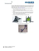
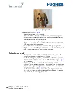
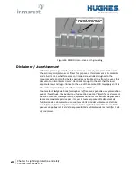
Figure 43: Adjusting azimuth
To adjust azimuth, refer to
4.
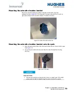
Loosen the two bolts on the pole collar.
5.
Move the ODU to either side, in small increments, as necessary to get the
optimum signal strength as shown on the voltmeter or by the fast high pitch
sounds that you hear with the headphones.
When you have maximized the signal quality:
6.
Tighten the two bolts in the curved slots on the azimuth elevation bracket to
lock down the elevation adjustment.
7.
Be careful not to change the ODU’s orientation while tightening the bolts.
8.
Tighten the two bolts on the pole collar to lock down the azimuth adjustment.
9.
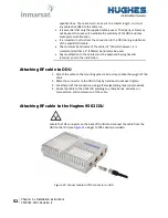
Make sure all other fasteners on both brackets are tight.
Exit pointing mode
1.
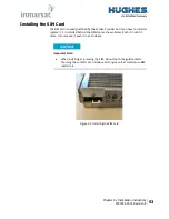
Short press the function button (<2 seconds) to exit pointing mode. The
terminal will initiate registration with the network.
2.
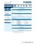
Verify the unit registers, attaches, and establishes a PDP context by checking
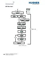
the status on the Web UI or when all three of the LEDs are solid green (
3.
Optionally, verify the unit will correctly recover from a power cycle by
removing and reapplying power. Verify it registers, attaches, and establishes a
PDP context by again checking the status on the Web UI or when all three of
the LEDs are solid green (
on page 62).
4.
Verify end to end connectivity of the system, by sending a small amount of
data from the device connected to the 9502 and verifying that the data was
received by the other end (e.g., data center).

