XDM® -100
Physical Description
417006-2005-013-A02
ECI Telecom Ltd. Proprietary
7-5
TC (Tributary Control) and TCF (Tributary Control and Fans) Modules
The TC or TCF provides control and cooling (TCF only) to the TPMs in the TPU
shelf. The module is connected to the MXC power and control buses through the
backplane of the TPU. Control signals received from the active MXC card are
processed by the TC or TCF and sent as control for activating the protection relays
on the TPMs.
The TCF contains four fans that provide cooling air to the TPMs. It also controls the
speed of the fans according to the ambient temperature. A power converter on the
module generates the required DC voltages for the fans and the module circuits.
7.1.3 Nonredundant XDM-100 Shelf Layout
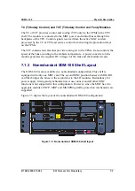
The XDM-100 is also available in a nonredundant configuration. This shelf is
equipped with only one MXC card. The second MXC position houses an MXC-BG
card that bridges the buses of the second slot to the I/O modules. Redundancy for
power supply, timing and synchronization, cross-connect and all other MXC
functions is not supported in this configuration. However, since the MXC has two
aggregate modules, SNCP, MSP, and MS-SPRing traffic protection mechanisms are
supported.
7-3 depicts the layout of the nonredundant XDM-100 configuration.
CRT
MON
ACT
FA
IL
MAJ
MIN
WAR
U SB
ALA RMS
D EBU G
F -C HA NN EL
T 3_1/ T4_1
T3_2 /T4 _2
MNG
MNG
MAI N
PR OT
MOD ULE
CH AN NE L
ECU
S TM 1
MON
LAS ER
A CTI VE
L ED
TES T
A CO
AC
FL
TR
MAI N
AC T
FA I L
TMU
NV M
MXC-100
POWER IN A
POWER IN B
A DB
A C
FL
T R
P IM 34 5 _3
I N1
IN 2
I N3
O U T1
OU T2
OUT 3
M O N
M O N
M O N
MON
AC
FL
TR
P IM2 _2 1
MON
I N 1- 21
OUT 1-21
MO N
AC
FL
TR
P IM2 _ 21
MON
OU T 1-21
IN 1 -21
MON
AC
FL
TR
P IM2 _2 1
MON
I N 1-21
OUT 1-21
MO N
N VM
RE SE T
OUT 1
I N1 O U T2
IN 2
OU T3
I N3 OUT4
IN 4
ON
MO N
ON
MON
ON
MON
ON
MO N
S A M1 _ 4/0
A C
F L
TR
S A M4 _ 2
OU T1
I N1 OUT 2
IN 2
ON
ON
MO N
MON
MO N
XDM -100
A CT IV E
F A IL
FC U
R
LA SER K LASS E 1
CLASS 1 LAS
ER PR
ODUCT
HAZARD CLAS
S 1
M
LASER RADIATION
WHEN OP
EN A
VOI D
EXPOSURE TO THE BEAM
- +
- +
W ARN ING !!!
R E MO V E S AM /O S C
MO DU L E S
BE FO RE CA RD
E X T RA C T IO N
Figure
7-3: Nonredundant XDM-100 shelf layout
Summary of Contents for XDM-100
Page 1: ...XDM 100 Miniature MSPP for Metro Access and Cellular Networks General Description ...
Page 3: ...XDM 100 ...
Page 8: ...Contents XDM 100 iv ECI Telecom Ltd Proprietary 417006 2005 013 A02 ...
Page 10: ...Contents XDM 100 vi ECI Telecom Ltd Proprietary 417006 2005 013 A02 ...
Page 12: ...Contents XDM 100 viii ECI Telecom Ltd Proprietary 417006 2005 013 A02 ...
Page 16: ...Introduction XDM 100 1 4 ECI Telecom Ltd Proprietary 417006 2005 013 A02 ...
Page 22: ...Applications XDM 100 2 6 ECI Telecom Ltd Proprietary 417006 2005 013 A02 ...
Page 30: ...System Characteristics XDM 100 3 8 ECI Telecom Ltd Proprietary 417006 2005 013 A02 ...
Page 44: ...System Design XDM 100 4 14 ECI Telecom Ltd Proprietary 417006 2005 013 A02 ...
Page 82: ...XDM 100H XDM 100 8 8 ECI Telecom Ltd Proprietary 417006 2005 013 A02 ...
Page 94: ...Glossary XDM 100 B 6 ECI Telecom Ltd Proprietary 417006 2005 013 A02 ...
Page 98: ...Index XDM 100 I 4 ECI Telecom Ltd Proprietary 417006 2005 013 A02 ...


