960E
Installation Manual
ECI Telecom Ltd. Proprietary
18
5.2. Power
Connector
Connection
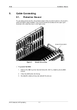
Figure 10.
Power Connector Connection
The Power Connector is located in the center of the Central Connection Panel as shown
in the figure above. The power cable is supplied with the system; see "Orderable Items"
(on page 32).
The terminals are labeled "-, Power A, +"; " -, Power B, +".
One power source is sufficient to operate the 960E.
The 960E has an option for two alternate -48/60V
DC
power sources, A and B. If one power
source fails or is not connected, the shelf can operate from the other single source. For
only one power source connection, connect to -A and +A.
The shelf does not operate if power leads are reversed, although no damage can occur to
the shelf.
¾
To connect the DC power cables:
1. Insert the cable in socket PWR A.
2. Secure the screws on both sides of the plug.
3. Repeat for PWR B.
5.3. Clock
Reference
¾
To connect the clock cable:
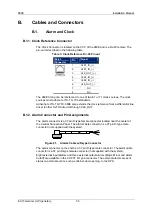
1. Insert the RJ-45 connector cable into the external clock port on the 960E CCP.
2. Connect the other end of the cable to the external equipment.
5.4. Alarm
Connection
¾
To connect the alarm cable:
1. Insert the 37-pin alarm connector cable into the Alarm port on the 960E CCP.
2. Use slot-head 5x150 mm screwdriver to secure the connector.
3. Connect the other end of the cable to the Alarm panel in the rack mount.
A
B


