960E
Installation Manual
ECI Telecom Ltd. Proprietary
30
A. Maintenance
A.1.
Replacing the Fans
The 960E arrives with the fan unit installed. The fan unit is located under the cards
and is secured to the frame with two screws on the left and right of the fan unit.
The Fan Module in the 960E contains the Fan Assembly and the Fan Control Card.
The Fan Assembly contains six fans measuring 120 x 120 x 38mm. The Fan Card
controls the fan operation. Fan operation, including fan speed and Start/Stop modes,
is software-configured via the NI card.
The Fan Module can be replaced while the shelf is operation. It should be replaced
within few minutes to avoid failures due to over temperature.
When removing the module, it is recommended disengaging the module first, waiting
a few seconds until the fans stop spinning and then removing it.
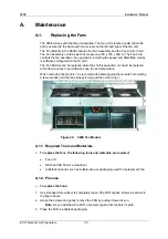
Figure 20.
960E Fan Module
A.1.1. Required Tools and Materials
¾
To replace the fans, the following tools and materials are required:
•
Fan unit
•
Slot-head 5x150 mm screwdriver
•
Antistatic material, such as bubble-wrap or packaging used for replacement fan.
A.1.2. Process
¾
To replace the Fans:
1. Use slot-head screwdriver to completely loosen the FAN captive screws as shown in
the figure above.
2. Grasp the screws and gently remove the FAN by pulling it towards you.
Note
: As you withdraw the FAN, note metal guide that controls its path.
3. Place the FAN in antistatic packaging.

