background image

960E 

Installation Manual 


ECI Telecom Ltd. Proprietary 

39 


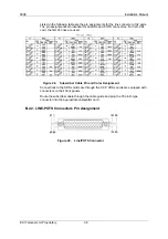
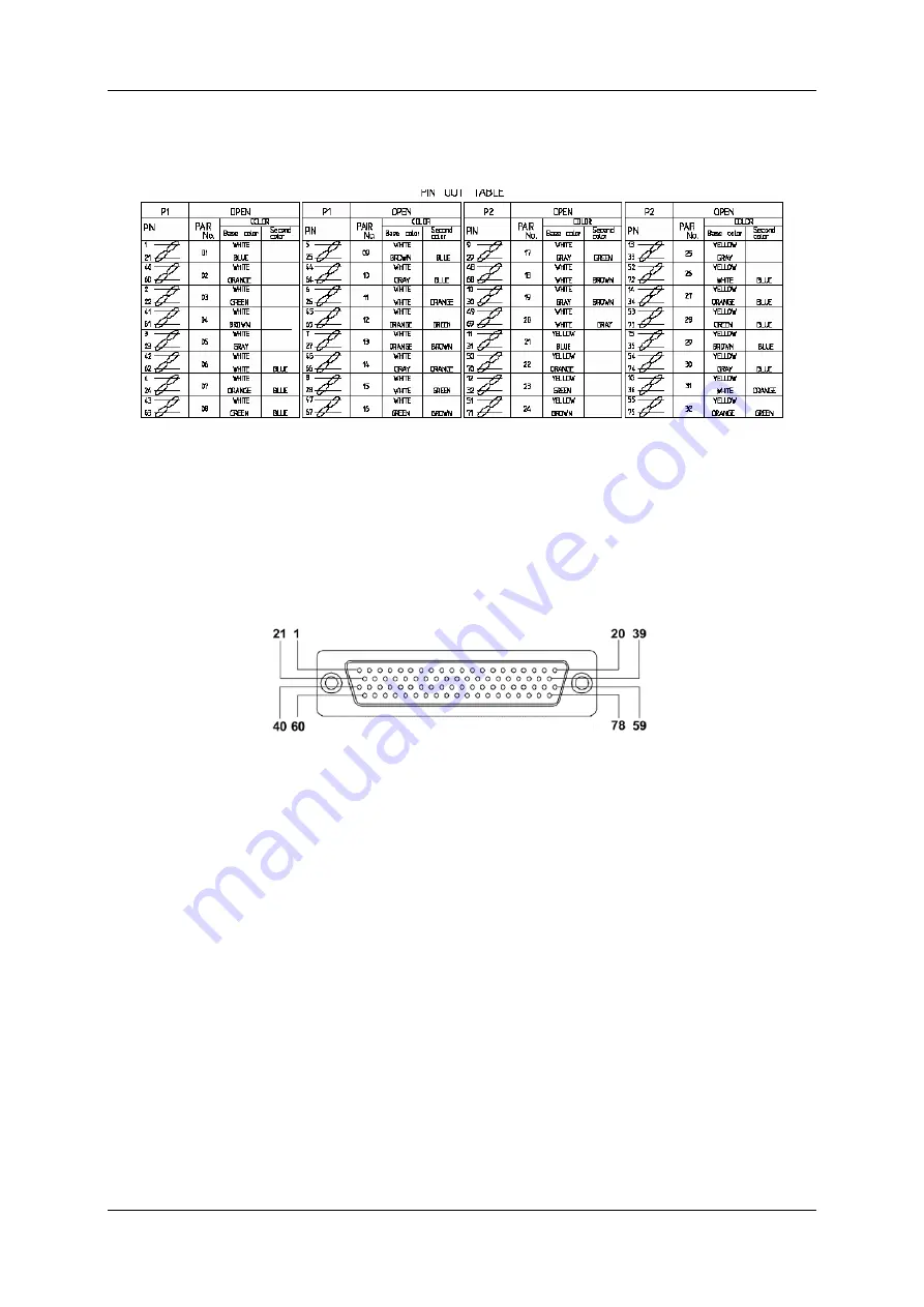
Listed in the following table are the pin assignments for the line connector of 32 pairs. 
The pin assignments are identical for all xDSL and POTS connectors. For V2U-C24 
card, the first 24 lines are used. 


Figure 28. 

Subscriber Cable Pin and Color Assignment 

Connections to the ADSL cards are through the CCP. VDSL cards are equipped with 
connectors on their front panels. 

Route the subscriber cable through the cable guide and plug the 78 pin D-type 
connector into the appropriate line/splitter card. 

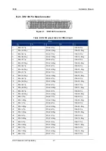
B.2.2. LINE-POTS Connectors Pin Assignment 


Figure 29. 

Line/POTS Connector 

Summary of Contents for Hi-FOCuS 960E

Page 1: ...960E Installation Manual ECI Telecom Ltd Proprietary i Hi FOCuS 960E Installation Manual ...

Page 2: ... or disclosed to third parties and you may not rent lease sell transfer or otherwise dispose thereof in whole or in part without the express prior written permission of ECI In addition any use of this document or disk or the information contained herein for any purposes other than those for which it was disclosed is strictly forbidden ECI reserves the right at any time without notice or liability ...

Page 3: ...o disconnecting device between the grounded circuit conductor of the DC source return line and the point of connection of the grounding electrode Be sure to exercise proper Electrostatic Discharge ESD precautions when handling the unit Electrical Safety Hazards The DC power 48 60 VDC supplied to the unit from a local power source should have a readily accessible listed branch circuit over current ...

Page 4: ...o electronic components SFP should be placed directly into protective packaging upon removal from equipment A replacement SFP shall be kept in its protective packing until required for immediate installation into equipment The field service operator should insure that the materials and tools necessary to maintain and control the temporary ESD Protected Area EPA are available at the place of the fi...

Page 5: ... 2 INSTALLATION OVERVIEW 7 3 SITE PREPARATION AND PRE INSTALLATION 8 3 1 PRELIMINARY SITE SURVEY 8 3 2 REQUIRED TOOLS ACCESSORIES 9 3 3 CHECKLIST 9 3 3 1 List of Cables 9 3 4 SITE REQUIREMENTS 10 3 4 1 Rack Mounting Guidelines 10 3 4 2 Minimum Distances between Cabinets 10 3 4 3 Requirements 10 3 5 UNPACKING AND VISUAL INSPECTION 10 3 5 1 Before you start 10 3 5 2 To unpack the equipment 11 3 5 3 ...

Page 6: ...AINTENANCE 30 A 1 REPLACING THE FANS 30 A 1 1 Required Tools and Materials 30 A 1 2 Process 30 A 2 INSTALLING AND REMOVING THE AIR FILTERS 31 A 2 1 Process 31 A 2 2 Removing the SFP Transceiver 31 A 2 3 Installing the SFP Transceiver 31 A 3 LIST OF ORDERABLE ITEMS 32 B CABLES AND CONNECTORS 33 B 1 ALARM AND CLOCK 33 B 1 1 Clock Reference Connector 33 B 1 2 Alarm Connector and Pin Assignments 33 B ...

Page 7: ...er pressing Space bar 27 Figure 16 Shelf card population 28 Figure 17 960E IPNI Card Version 28 Figure 18 960E ATUC Card Version 29 Figure 19 960E VTUC Card Version 29 Figure 20 960E Fan Module 30 Table 3 Clock Reference RJ 45 Pin out 33 Figure 21 Alarms Cable w D type Connector 33 Figure 22 Alarm Connector 37 Pin D Type Male Pin out 34 Figure 23 In Alarm Connection Circuitry 36 Figure 24 Out Alar...

Page 8: ...960E Installation Manual ECI Telecom Ltd Proprietary viii Table 6 SFP Types 48 Table 7 Hi FOCuS Specifications table 51 Table 8 HF5 Cards Power Consumption 51 ...

Page 9: ...rm Connector Pin Assignment 34 Table 3 RS 232 DB 9 Connector Pin Assignment 43 Table 4 D type 5W5 pin list 43 Table 5 Power range displayed by LED and reported alarm bit 44 Table 6 Ethernet RJ 45 Pin out 45 Table 7 RS 485 Connector Pin Assignments 45 Table 8 CFU Card LEDs States and Definitions 49 Table 9 Acronym Table 50 ...

Page 10: ...ple Technologies Multiple Deployments Deployed in a Central Office CO the 960E serves as an infrastructure component within the network and aggregates traffic from other subtended Hi FOCuS shelves towards the network The 960E can also be deployed in Local Loop locations for direct to subscriber services In either case the 960E can mix subtending and direct to subscriber services for maximum deploy...

Page 11: ...960E Installation Manual ECI Telecom Ltd Proprietary 2 1 2 External Interfaces and Indications Figure 2 960E Shelf Unit Figure 3 960E Chassis ...

Page 12: ...IP IPNI IPNI PTU C64IP VoIP GPLT 4 GPON GPLT 4 GPON 960E_internal_Blocks vsd Figure 4 960E Front View with sample card configuration Fifteen tributary line cards can be installed in 15 slots The slots 16 and 17 are for two NI cards The 960E pluggable cards and modules and fixed units are Central Connection Panel Central Connecting Panel Power module Cable Organizer Main card compartment with tribu...

Page 13: ... copper connection to NI cards Copper uplink lines LINES DB 78 Male connector Accommodates up to 32 copper pairs to the subscriber lines DB 78 Female RS 232 RS 232 Female DB 9 connector Enables on site technician to connect a portable PC to the 960E Craft port over RS 232 RS 232 Male DB 9 ALARMS DB 37 Male Alarm connector for input alarms input clocks output alarms EU and output alarms NA DB 26 Fe...

Page 14: ... OPS 1 2 6 Clock Reference Connector The clock connector on the Central Connecting Panel is a RJ 45 female The 960E timing can be referenced to one of two E1 or T1 clock sources One source is alternate to the other The clock sources must adhere to ITU T G 703 standards Adhering to ITU T G703 960E also extends clock reference from a differential line driver to other Hi FOCuS units through CLK_OUT 1...

Page 15: ...ring Unit cards share the power load If one power source is missing the Central Filtering Unit of the other power source assumes the entire load If one Central Filtering Unit fails or is not installed the other Central Filtering Unit card assumes the entire load 1 2 10 Fan Unit The FAN unit contains six fans The Fan Module can be field replaceable without affecting traffic if the replacement is ac...

Page 16: ...e Chapter 7 Perform the commissioning procedure see Chapter 8 Install the SFP and connect the NI fiber optic cable to the SFP see Chapter 6 Connect the Ethernet cable optional see Chapter 6 Connect the Alarm cable see Chapter 6 Prepare and connect DC power cables Verify power wiring see Chapter 6 Installation Overview Flow Chart Mounting Ground and Power Cable Connections Powering Up Commissioning...

Page 17: ...her protected location sheltered location direct weather influences are not completely excluded Climate controlling system A system that controls or influences climate acting at least on one climatic parameter in one direction Heating system A system that controls or influences climate by increasing the air temperature only This can decrease the relative humidity Cooling system A system that contr...

Page 18: ...ls for installing the system Other tools might be needed in accordance with local conditions DVM Digital Volt Meter Set of screwdrivers flat and Phillips Terminal ring crimping tool GND Cable Wire stripper cutter 3 3 Checklist Verify that you have the following items 960E unit Cables as listed below 3 3 1 List of Cables Table 2 List of Cables Cables Quantity Included in Package Power Cable 1 or 2 ...

Page 19: ...minimum of 5 cm 2 in of clearance at both the inlet and exhaust vents on the chassis Keep the site as dust free as possible dust particles can clog the air filter and restrict airflow 3 4 3 Requirements See Appendix E for Power and Environmental Specifications 3 5 Unpacking and Visual Inspection 3 5 1 Before you start Before unpacking make a preliminary inspection of the shipping boxes Evidence of...

Page 20: ... Check for loose parts or any visual damage to the rack shelf and auxiliary equipment Also check the integrity of all the connectors leads and cables  Note Do not remove plastic covers from optical connectors until the optical fibers are connected to them Search the shipping boxes for any additional small items that may be present Check the contents of the shipping boxes against the packing list ...

Page 21: ... are similar The rack mounting brackets for ETSI racks can be inversed and uses for 19 racks 4 2 1 Rack Installation ÂNote Two technicians are recommended to mount the 960E in the rack to properly position and attach the rack ÂNote The recommended minimum distances between shelves to allow proper air circulation and cable bending clearance are Top and Bottom 10 cm clearance between shelves Right a...

Page 22: ...960E Installation Manual ECI Telecom Ltd Proprietary 13 Figure 7 Mounting bracket and position ETSI shown ETSI Mounting Bracket Screw holes for mounting in middle positioning rack mounts ...

Page 23: ...ts adjacent to the 960E The space between the 960E and other units below or on top of it can be as little as 100mm Power Distribution Frame Splitter 960 Direct connection between Shelves Hi FOCuS 960E Optical Distribution Frame 960E_Rack_Mount1 vsd Figure 8 960E in an ETSI Rack ...

Page 24: ...only in the dedicated NI slots NI cards are installed in the 16 and 17 A and B slots For only a single NI card insert the card into slot 17 To install the GPLT 4 card 1 Remove the GPLT 4 card from its anti static package Take care not to touch the surface of the line card 2 Raise the locking levers on both ends of the card 3 Align the GPLT 4 card with the guide rails in the 960E frame and push the...

Page 25: ... 15 4 4 Central Filtering Unit Installation The Central Filtering Unit CFU cards module has two CFU cards CFU A and CFU B located at the bottom left hand corner of the shelf The CFU card filters the 48 60VDC power feed supporting dual power filtering and redundancy If two power sources are used the CFU cards share the power load If one power source is missing the CFU of the other power source assu...

Page 26: ...lf in which the 960E is being installed The ground connection is located on the upper right hand side of the shelf as shown in the figure below Figure 9 Ground Connection To ground the 960E 1 Remove the GND lug from the shelf below the CCP by releasing the two ESD screws 2 Crimp the GND cable into the lug 3 Re install the cable with lug secured with the screws Ground Connection ...

Page 27: ... single source For only one power source connection connect to A and A The shelf does not operate if power leads are reversed although no damage can occur to the shelf To connect the DC power cables 1 Insert the cable in socket PWR A 2 Secure the screws on both sides of the plug 3 Repeat for PWR B 5 3 Clock Reference To connect the clock cable 1 Insert the RJ 45 connector cable into the external c...

Page 28: ... panels  Note Cables with right angle connectors must be used when installing the 960E to allow proper clearance during re installation of the front cover Figure 11 Cable w Straight Connector right_angle_plug Figure 12 Cable w Right Angle Connector The 960E contains a fiber cable guide with 17 slots for the 17 line NI cards Figure 13 Fiber Cable Guide straight_plug Cable Guides ...

Page 29: ...Route the fiber optic cable through the fiber guide 2 Plug it into the SFP connector on the NI card 3 Connect the other cable side to the Ethernet equipment 4 For simplex fiber optic cables make sure the Tx and Rx ports are cross connected Caution Fiber optic cables and assemblies should be treated carefully and kept clean see appendix B 4 2 5 5 3 GPON Optical Cable To connect the GPON Optical cab...

Page 30: ...the card panel 3 Use slot head 5x150 mm screwdriver to secure the connector 5 6 Management Interface Out of band management is conducted through a 100Base T RJ45 connector Ethernet port Port A connects to IPNI A and port B connects to IPNI B To connect the Ethernet cable 1 Connect RJ 45 plug connector of the cable to the Ethernet 1 port on the 960E CCP 2 Connect the other cable side to the Etherne...

Page 31: ...nected 2 Ensure all cables are bundled properly and the spacing between cable ties is appropriate 3 Ensure the cable ties are not overlaid and have no sharp ends Check cables and optical fibers 1 Ensure the cables are not stretched too tightly at turn points 2 Ensure the wiring route is correct and cables are bundled with the same intervals 3 Ensure the cables inside the rack are straight and smoo...

Page 32: ...ceed with the following procedures 1 Turn on the power of the rack that supplies power to the 960E The fan unit of the 960E starts running If the fans in the chassis are not running normally cut off the power and check the fans 2 Turn off the power of the rack and then re insert the cards into the backplane ...

Page 33: ...erminal is turned on 2 Turn on the power source The 960E starts running the cooling fans initializes the system and indicates system statuses on the IPNI LEDs The duration of system initialization can take a few minutes Warning The cover must be re installed to ensure proper air flow cooling and EMC Electro Magnetic Compatibility standards See section Front Cover Installation for cover installatio...

Page 34: ... laptop or a PC terminal with a serial cable connected to a COM port RS 232 To Define a Terminal Connection 1 Connect the RS 232 Terminal port of the 960E with the PC COM port 2 Launch a HyperTerminal session on the PC as follows from the Windows Start menu select Programs Accessories Communication HyperTerminal 3 The HyperTerminal window opens and prompts for a connection name 4 Type a connection...

Page 35: ...tion contains instructions for setting various parameters for out of band or in band configurations Any changes made to the parameters will be activated only after ees and the NI card has been rebooted Obtain the IP Address and IP Gateway from your system administrator To set out of band configuration parameters 1 Set the IP Address and IP Gateway by typing ethernetip ipaddress gateway subnetmask ...

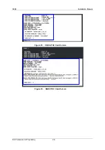
Page 36: ...s the Ethernet default gateway 3 Set the management VLAN by typing sinvlan vlan id 1 4094 untagged vlan priority 0 7 and then press Enter 4 Save the parameters by typing ees and then press Enter 5 Reboot the 960E by typing restart at the command prompt and then press Enter 8 4 Sample Screens Figure 14 Screen shot after typing eer and pressing Enter Figure 15 Screen shot after pressing Space bar ...

Page 37: ...view the shelf card population 1 Type getpop 0 Figure 16 Shelf card population 8 6 960E SW HW Version To view the IPNI card version 1 Type ver Figure 17 960E IPNI Card Version To view the ATUC VTUC SW HW version 1 Type XTUCTERM 0 7 2 Type in any Login and Password Press Enter 3 Type ver ...

Page 38: ...960E Installation Manual ECI Telecom Ltd Proprietary 29 Figure 18 960E ATUC Card Version Figure 19 960E VTUC Card Version ...

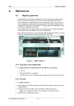
Page 39: ...ion It should be replaced within few minutes to avoid failures due to over temperature When removing the module it is recommended disengaging the module first waiting a few seconds until the fans stop spinning and then removing it Figure 20 960E Fan Module A 1 1 Required Tools and Materials To replace the fans the following tools and materials are required Fan unit Slot head 5x150 mm screwdriver A...

Page 40: ...se this process to replace the air filter A 2 2 Removing the SFP Transceiver To remove the SFP Transceiver 1 Have anti static package ready for the SFP Transceiver being replaced 2 Make sure you are wearing an ESD strap and that it is connected to the ESD jack of the 960E chassis 3 To extract the SFP Transceiver pull outward on its ejector and pull the SFP Transceiver slowly towards the right 4 Pl...

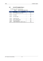
Page 41: ...orderable items Table 1 List of Orderable Items USA Part No Accessory Quantity Provided Y22853 SFP TRANSCEIVER 15KM DTAG 8 NO Y33038 V2U C24EC 1 NO Y43520 ATU C64IP ISDN 1 NO Y33096 IPNI 80E R3 DTAG 1 NO Y33097 SHELF SAM 960E DTAG 1 Yes Y33098 CFU FOR SAM 960E 1 Yes Y12417 CABLE POWER 5W5 TO OPEN 3 Meters 1 Yes ...

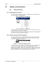
Page 42: ... the clock reference from a differential line driver to other Hi FOCuS units through CLK_OUT B 1 2 Alarm Connector and Pin Assignments The alarm connector is a 37 pin D type female connector located near the center of the Central Connection Panel The alarm cable connector is a 37 pin D type male connector not supplied with the system Figure 21 Alarms Cable w D type Connector The alarm connector on...

Page 43: ...rietary 34 Figure 22 Alarm Connector 37 Pin D Type Male Pin out Table 2 Alarm Connector Pin Assignment 1 DC_AC_NO IN_ALR1 20 2 DC_MI_NO IN_ALR2 21 3 DC_MA_NC IN_ALR3 22 4 IN_ALR4 23 5 CGND IN_ALR5 24 6 IN_ALR6 25 7 IN_ALR7 26 8 IN_ALR8 27 9 28 10 ...

Page 44: ...llation Manual ECI Telecom Ltd Proprietary 35 29 11 NAMIA_NC 30 12 EUMIA_CO 31 13 EUMIA_NO N48V_LIM 32 14 EUMAR_CO 33 15 EUMAR_NC P48V 34 16 EUMAV_CO 35 17 EUMAV_NC ALM_COMM 36 18 NAMAV_NO DRY_COMM 37 19 NAMAR_NO ...

Page 45: ... circuit connection P48VDC nominally is required for each in alarm and 48 60VDC for common CPA IPNI CCP ALM_COMM IN_ALR1 IN_ALR2 IN_ALR3 IN_ALR4 IN_ALR5 IN_ALR6 IN_ALR7 IN_ALR8 48 60VDC P48VDC P48VDC P48VDC P48VDC P48VDC P48VDC P48VDC P48VDC Alarm_Connection_circuitry vsd Figure 23 In Alarm Connection Circuitry ...

Page 46: ... installations NA alarms have 3 contacts NC NA and COM EU alarms have 2 contacts DRY COMM and NO or NC Major alarm is NC and the alarm is active when power is down or when the system software indicates a Major alarm Minor and ACO alarms are NO and active when the system software indicates a Minor or ACO alarm respectively Figure 24 Out Alarm Connection Circuitry ...

Page 47: ...nce during re installation of the front cover Figure 25 Cable w Straight Connector right_angle_plug Figure 26 Cable w Right Angle Connector Subscriber copper connections are 78 pin male D Type connectors at the shelf This 78 pin connector is used for all technologies ADSL2 VDSL2 and POTS It is used for either 24 pairs or 32 pairs Each connector serves either 24 or 32 pairs Figure 27 Line Connector...

Page 48: ...rs For V2U C24 card the first 24 lines are used Figure 28 Subscriber Cable Pin and Color Assignment Connections to the ADSL cards are through the CCP VDSL cards are equipped with connectors on their front panels Route the subscriber cable through the cable guide and plug the 78 pin D type connector into the appropriate line splitter card B 2 2 LINE POTS Connectors Pin Assignment Figure 29 Line POT...

Page 49: ... 7 Tip White 14 Ring Gray Orange 66 27 Ring Orange Brown 13 Tip White 47 8 Tip White 16 Ring Green Brown 67 28 Ring White Green 15 Tip White 48 9 Tip White 18 Ring White Brown 68 29 Ring Gray Green 17 Tip White 49 10 Tip White 20 Ring White Gray 69 30 Ring Gray Brown 19 Tip Yellow 50 11 Tip White 22 Ring Orange 70 31 Ring Blue 21 Tip Yellow 51 12 Tip Yellow 24 Ring Brown 71 32 Ring Orange 23 Tip Y...

Page 50: ...g DSL 21 Ring DSL 33 Ring 11 DSL 46 Tip DSL 35 Tip DSL 32 Tip 12 DSL 46 Ring DSL 35 Ring DSL 32 Ring 13 DSL 48 Tip DSL 22 Tip DSL 31 Tip 14 DSL 48 Ring DSL 22 Ring DSL 31 Ring 15 DSL 40 Tip DSL 30 Tip DSL 26 Tip 16 DSL 40 Ring DSL 30 Ring DSL 26 Ring 17 DSL 3 Tip DSL 27 Tip DSL 25 Tip 18 DSL 3 Ring DSL 27 Ring DSL 25 Ring 19 DSL 9 Tip DSL 29 Tip DSL 24 Tip 20 DSL 9 Ring DSL 29 Ring DSL 24 Ring 21 ...

Page 51: ...al ECI Telecom Ltd Proprietary 42 DSL a b c d e 30 DSL 2 Ring DSL 11 Ring DSL 15 Ring 31 DSL 1 Tip DSL 6 Tip DSL 10 Tip 32 DSL 1 Ring DSL 6 Ring DSL 10 Ring B 2 4 ADSL2 Front Connector Figure 32 ADSL2 Front Connector pinout ...

Page 52: ...andard power feed module for the 960E is the High current Input Filter dual source power feed module supported with two Central Filtering Unit CFU card modules Each CFU card supports both power sources Hence there is redundancy in the power source and in the CFU card The High current Input Filter power input module and the Central Filtering Unit cards are designed for a maximum of 2500 W Supplied ...

Page 53: ... ON 0 1 Under voltage 30 V 37 V OFF ON 0 1 B 4 Telecom B 4 1 Traffic Cables Network and Subscribers The NI card connection to the network is via fiber optic cables at the NI card front panel Tributary line card connections to subscribers are via the front panel connectors B 4 2 Fiber Optic Cables The fiber optic cable and connector type is LC PC Duplex Single Mode 9 125 and Normal Fiber optic cabl...

Page 54: ...hernet connection is used for management and monitoring The pin out is described in the following table Figure 35 CP Ethernet A and B RJ 45 Connectors Table 6 Ethernet RJ 45 Pin out Pin Signal 1 ETH TX H 2 ETH TX L 3 ETH RX H 4 A_ETH_TXH 5 A_ETH_TXL 6 ETH RX L 7 A_ETH_RXH 8 A_ETH_RXL B 4 4 RS 485 Connector The RS 485 connector is for external control such as automatic MDF The RS 485 connector pin ...

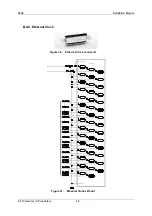
Page 55: ...960E Installation Manual ECI Telecom Ltd Proprietary 46 B 4 5 Ethernet Clock Figure 36 Ethernet Clock connector Figure 37 Ethernet Clocks Pinout ...

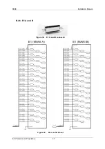
Page 56: ...960E Installation Manual ECI Telecom Ltd Proprietary 47 B 4 6 E1 A and B Figure 38 E1 A and B connector Figure 39 E1 A and B Pinout ...

Page 57: ...the SFP cage The SFP types applied to the 960E are listed below Table 6 SFP Types Interface Optical Receiver Sensitivity Wavelength Connector Type Transmission Distance Vs Cable Specifications 1000BASE SX 17dBm 850nm LC 550m 50um MMF 1000BASE LX I 22dBm 1310nm LC 10Km 10um MMF 1000BASE LX L 22dBm 1310nm LC 20Km 10um MMF 1000BASE LX E 22dBm 1310nm LC 40Km 10um MMF 1000BASE ZX 24dBm 1550nm LC 80Km 1...

Page 58: ...rd LEDs States and Definitions LED Color State Definition Remarks On 38VDC Input Voltage 75 VDC Input voltage in range Power Green only Off 38VDC Input Voltage 75 VDC Input voltage out of range On 40 5VDC Input Voltage 75VDC Voltage warning Alarm Red only Off 40 5VDC Input Voltage 75VDC Input power okay if power LED is on ...

Page 59: ...Telecommunications Standards Institute FCC Federal Communications Commission GND Ground HFFR Halogen Free HIF High current Input Filter IP Internet Protocol ITU T International Telecommunication Union LVDS Low Voltage Differential Signaling MAC Media Access Control MANI Multiplexed Aggregate Network Interface MDF Main Distribution Frame NI Network Interface OPS Operator Station POTS Plain Old Tele...

Page 60: ... lbs unpopulated 50 kg 110 lbs fully populated Power Power Source 40 5 to 75 VDC Power Consumption fully populated 2500W Environmen tal Operating Temperature 40 C to 70 C Storage temperature 40 C to 70 C Relative Humidity Operating humidity 93 RH Storage humidity 95 RH Operation Compliant with ETS 300 019 2 3 Class 3 4 temperature controlled locations and ETS 300 019 2 3 Class 3 1E Transportation ...

Page 61: ...nd the Council of the European Union on waste electrical and electronic equipment WEEE and in jurisdictions adopting that Directive is marked as being put on the market after August 13 2005 and should not be disposed of as unsorted municipal waste Please utilize your local WEEE collection facilities in the disposition of this product and otherwise observe all applicable requirements ...

Reviews: