background image

Firmware V3.00

05.08.2019

75/100

8.3.1  Menus and operating screens

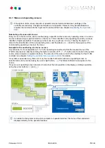
Numbering of menus and screens:

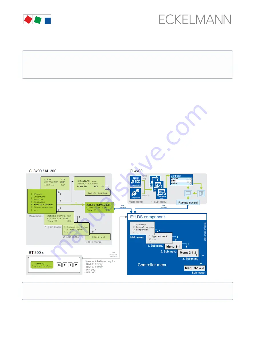
Every menu in the menu tree can be reached using a specific number and every operating screen in a menu 
can be reached using a specific selection in the menu. This is identified in the operating manual by a unique 
identifier of digits (and letters if necessary) in the menu tree (e.g. Menu 3-1-2-a). Thereby, the digits 1, 2, .. 
stand for the identification of the corresponding menu, and the letters a, b, .. stand for the sequence of the 
corresponding operating screens in the menu.

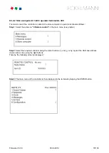
Example for the numbering of a menu / screen

Any reference to, for example Menu 3-1-2 in the operating manual means that the required menu of the 

E*LDS component is called by entering the digits or selection of "3 - 1 - 2" via the remote control in the system


centre, store computer or operator interface. The menu item "Remote control" is the interface for the E*LDS


controller; see chapter 

Calling the controller menu via remote control

 for details.

If any letter is appended (e.g. Menu 3-1-2-a), this means that another submenu (operating screen or 

selection list) can be reached using the cursor right button ( → ). The letters indicate their sequence in the


screen.
If any menu or operating screen consists of more lines than are possible in the display, scrolling is possible 

using the cursor buttons ( ↑ ) and ( ↓ ).

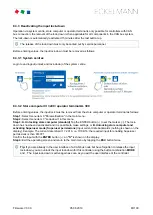
If the system centre, store computer or operator terminal remain locked down, settings on the 
controller are read-only. Changes and inputs are not possible. However, if any parametrisation is 

required, the lock-down for the input must be removed first, see chapter 

Deactivating the input lock-

down

.

In contrast to the system centre, store computer or operator terminal, the menu of the controller is 
displayed directly on the operator interface.

Summary of Contents for UA 410 L Series

Page 1: ...Firmware V3 00 05 08 2019 Documentation Version 3 1 Operating instruction Temperature Data Logging Controller UA 410 L ...

Page 2: ...ion and FAQs are available for you on line in E EDP Eckelmann Electronic Documentation Platform at www eckelmann de elds https edp eckelmann de edp lds _Y2OqwfWgBx Information on safety and connection instructions are described in detail in chapter Industrial safety notes Copyright All rights to any use whatever utilisation further development forwarding and creation of copies remain with the Ecke...

Page 3: ... 15 4 Application of UA 410 L 16 4 1 Versions 16 4 2 Controller type 17 4 3 Updating firmware 17 5 Function of UA 410 L 18 5 1 Starting characteristics 18 5 1 1 First start reset controller to factory settings 18 5 1 2 Restart restart of the controller 18 5 2 Selection of the temperature sensors 19 5 2 1 Required and optional sensors 20 5 3 Controller function 20 5 3 1 Cooling solenoid valve 20 5 ...

Page 4: ... DIP switch 53 6 6 3 Rectification of driver problems 57 7 Pin and Terminal Assignments of UA 410 L 58 7 1 Terminal diagram 58 7 2 Terminal assignment of the 230 V AC power supply 59 7 3 Terminal assignment of the 230 V AC relay outputs 60 7 4 Mode of operation of the relay and transistor outputs 61 7 5 Terminal assignment of the 230 V AC digital inputs 62 7 6 Terminal assignment of the 0 10 V ana...

Page 5: ...o Rx 0 83 9 2 Main menu 84 9 3 Menu 1 Actual Value 85 9 4 Menu 2 Setpoints 85 9 5 Menu 3 Clock 86 9 6 Menu 4 Messages 87 9 7 Menu 5 Archive 88 9 8 Menu 6 Configuration 89 10 Decommissioning and disposal 91 10 1 Decommissioning Dismantling 91 10 2 Disposal 91 11 Alarms and Messages of UA 410 L 92 11 1 Alarm signaling and monitoring 93 11 1 1 High or low temperature alarm 93 11 1 2 Disabling high or...

Page 6: ...Firmware V3 00 05 08 2019 6 100 13 Order numbers and accessories of UA 410 L 100 13 1 Case Controller 100 13 2 Accessories 100 ...

Page 7: ...Firmware V3 00 05 08 2019 7 100 ...

Page 8: ...vere injury or death if the specified instructions are not observed WARNING Instructions with this symbol and or the signal word WARNING warn the user of situations that may cause severe injury or death if the specified instructions are not observed CAUTION Instructions with this symbol and or the signal word CAUTION warn the user of situations that may cause moderate or minor injury if the specif...

Page 9: ...ple and the environment 1 2 Explanation of text formatting Safety instructions or hazard warnings are composed of four elements 1 The symbol with text e g for DANGER 2 a concise description of the hazard and 3 a description of the possible consequences 4 Where applicable a catalogue with measures for avoiding the hazard For example A general instruction consists of two elements 1 The symbol with t...

Page 10: ...g the device check whether it is suitable for your application with regard to its limit values The equipment must be installed in an electrically shielded area within the switch cabinet Before connecting the device it must be checked whether the power supply is suitable for the device When using uncoded plug connectors it is possible to connect them so that there is a danger to life and limb If th...

Page 11: ...0100 0113 must be observed The operating personnel must be instructed in how to handle the system machine and the controller and must be familiar with the operating instructions WARNING Warning of damage to goods and fire 1 In our experience the transmission of fault messages is not yet functional during the putting into service no internet connection no telephone line installed etc It is strongly...

Page 12: ... strictly observed 1 Disconnect The entire system to be worked on must be disconnected from the power supply at all poles 2 Secure against reconnection Attach information signs to the disconnected operating equipment stating What has been disconnected Reason for the disconnection Name of the person who made the disconnection Reconnection must be prevented using a suitable lock e g padlock 3 Prove ...

Page 13: ... leather soles Use the following Conductive flooring ESD workstations equipped with suitable tools grounded soldering guns antistatic wrist straps etc Conductive ESD bags conductive plastic containers IC tubes or cartons lined with conductive foam Containers and worktops made of wood metal or conductive plastics or paper bags 2 6 Abbreviations used DGUV Regulation 3 Accident Prevention Regulation ...

Page 14: ...offers the redundant temperature recording required by the standard In order to fully utilise its performance features the controller is typically connected to the CAN bus through which it communicates with further control and monitoring components across the entire network Via the CAN bus an intelligent data exchange is carried out with the following system components System Centre Store computer...

Page 15: ...LDS System new version DISPLAY Connection for BT 300x Operator Interface and up to four BT 30 Temperature Displays CI 320 Communication with LDSWin software Connection to the legacy system CI 320 USB For conducting a firmware update Inputs outputs 4 digital inputs 230 V AC floating 10 analog inputs Connection for two wire NTC temperature sensors Only UA 410 AC 2 x analogue inputs 4 20 mA currently...

Page 16: ...real time clock lithium cell power reserve With integrated archive memory for data recording 2 analogue inputs 4 20 mA currently without function 2 analogue outputs 0 10 V currently without function Abbreviations used AC stands for All in one and Cabinet DIN rail mounting All with CAN bus and real time clock i e C cabinet mounting Special feature The controller is available in two device generatio...

Page 17: ...perated by Host computer e g via network modem with connection to the system centre store computer the system centre a store computer or an operator terminal a local operator interface BT 300 via the DISPLAY interface on the controller or a notebook PC with the PC software LDSWin connected via USB 4 3 Updating firmware The case controller is supplied with the current firmware ready for operation F...

Page 18: ...ory settings 5 1 2 Restart restart of the controller For a restart the device is restarted with all configured parameters and the CAN bus address set on the rotary switch A restart can be initiated using the following procedure disconnection and reconnection of the power supply Parameters mentioned in this section are described in the Menüstruktur section It will normally not be necessary to chang...

Page 19: ...sensors are identical K277 Temperature range 50 to 50 C 5K3A1Temperature range 0 to 100 C For details of the dimensions see chapter Mechanical data of the temperature sensor L243 5K3A1 Detailed information on the temperature sensors is contained in the data sheet Mechanical data of the temperature sensor L243 5K3A1 All due care must be exercised when installing temperature sensors Sensor leads nee...

Page 20: ...ted when sensor alarm priority is set to 0 and no alarm or message is generated when sensor alarm priority is set to 5 3 Controller function The sections following describe the various functions of the UA 410 L for control and temperature recording of refrigeration points 5 3 1 Cooling solenoid valve On off control Control is made by one temperature sensor the first five temperature sensors Rx 1 R...

Page 21: ...erature control with recording Rx 1 Rx 5 5 temperature sensors for cooling and defrosting with recording 5 3 1 2 Emergency operation In failure of temperature measurement or the control temperature sensors cooling switches to the continuous state ...

Page 22: ...0 05 08 2019 22 100 5 3 1 3 Temperature recording Rx 1 Rx 0 10 temperature sensors for temperature recording A separate sensor name can be assigned to each sensor for better identification of the measuring location ...

Page 23: ...e internal timer Menu 3 2 and requires temperature to be lower than defrost termination temperature The controller checks whether the condition for defrosting is fulfilled before defrosting is actually initiated The condition is Temperature of the temperature sensor lower than defrost termination temperature The next defrost cycle cannot be started before the safe defrost time defrost parameter ha...

Page 24: ...d in the alarm list with CAN bus address node number priority and plain text Priority 0 alarms are only entered in the alarm log Priority alarms are neither reported to the alarm server nor entered in the message log Alarm can be suppressed for a group of five sensors by means of the digital inputs Digital Input D21 22 can be used to suppress temperature alarms for sensors 1 5 and Digital Input D3...

Page 25: ...ailable as accessory is required for readout on a PC see the LDSWin operating instruction Temperature recording in the system centre store computer via CAN bus The UA 410 L records the temperature every 15 minutes and sends this for archiving via the CAN bus to the system centre store computer Data is archived for one year Only the temperature values of the sensors of the temperature zones Rx 1 an...

Page 26: ...ion DIN EN 12830 on monitoring temperatures in the means of transport warehousing and storage of quick frozen foodstuffs Use of the UA 410 L as a temperature recording controller is described below The UA 410 L is generally suitable for recording up to 10 temperatures in compliance with said Regulation In order to archive more than two temperatures the system centre store computer must support EU ...

Page 27: ...y the temperature recording controller is performed in the system centre store computer With all the recording interval is 15 minutes and data is archived for a period of one year Temperature sensors of type L243 must be connected to the UA 410 L for temperature recording in compliance with EU Regulation DIN EN 12830 Actual temperature control must always be performed by an independent case coldro...

Page 28: ...er is read out as follows CI 4x00 see menu 2 6 EU archives CI 3x00 see menu 3 Archive Furthermore it is possible to retrieve the archived temperatures from the system centre store computer using the PC software LDSWin and present them in graphic form see operating manuals of the system centre store computer and of the PC software LDSWin Values 3 to 10 of the EU Archive Zone parameter are to be use...

Page 29: ... last Sunday in March and October Software clock over CAN bus When connected to the CAN bus the software clock is cyclically synchronised from a higher level controller with real time clock system centre store computer or operator terminal 5 3 6 BT 30 temperature display Up to 4 BT 30 temperature displays can be connected to the case controller The connection is made via the connection DISPLAY ter...

Page 30: ...d temperature value is shown in the display for the duration of the defrost This also applies during any possibly set wait time The current temperature is not displayed again until 15 minutes after the end of the defrost The drip time does not extend this delay time of 15 minutes Symbol Snowflake Controller in cooling operation cooling active Symbol Alarm An alarm is pending In order to counteract...

Page 31: ...uctions Before the installation and commissioning of the controller the chapter Safety instructions must be carefully read in its entirety and all safety instructions and hazard warnings observed The controller should only be used with compatible versions of the LDSWin PC software otherwise the scope of functions can be restricted Tip The latest version of LDSWin should be used at all times ...

Page 32: ...ed regulation and control device EN60730 All leads running to and from the case controller especially those of the CAN bus must be shielded cable type LiYCY No shielding is required on sensor leads when installed exclusively inside the refrigerated display case and when external interference for example from parallel power wires is not to be expected see operating instruction Grundlagen und allgem...

Page 33: ...about dangerous electrical voltage Danger of electric shock The safety instructions and work safety instructions must be observed for the mounting All plug connectors may only be inserted and removed when the power supply is disconnected In order to carry out the assembly dismantling there must be a distance of at least 8 mm from the next component e g cable duct otherwise the retaining springs ca...

Page 34: ...e case controller is positioned on the lower edge of the DIN rail Step 3 Press in the two retaining springs until they click into place and checkthat the case controller is firmly attached to the DIN rail The controller can be put into operation after completion of the mechanical and electrical installation of the case controller ...

Page 35: ...etaining springs with a flat bladed screwdriver until they click into place Step 3 Remove the device from the DIN rail A by tilting it upwards Warning hazardous electrical voltage Danger of electric shock When disassembling the safety instructions and work safety instructions must be observed All connectors may only be connected and disconnected when power is off ...

Page 36: ...also possible The orange push button must also be pressed during insertion to connect flexible wires of 0 25 to 2 5 mm without wire end sleeve B Disconnetion The wires are disconnected using a screwdriver max 3 5 mm width via the orange push button at the terminal connection that has no direct contact to live parts Step 1 Press the orange push button vertically downwards using a screwdriver to det...

Page 37: ...CAN bus address DIP switch S3 Controller type setting Master Slave mode Setting of special functions see chapter Setting the controller type Settings AFTER application of the power supply Erstanlauf Regler auf Werkseinstellungen zurücksetzen optional setting to default values to reach a defined initial state for a running operation Configuration of the controller see chapter Grundkonfiguration des...

Page 38: ... CAN bus address S1 S2 30 4 34 Risk of confusion In order to avoid mix ups it is recommended to use the position number of the refrigerated case as CAN bus address A different CAN bus address that must be unique in this system must be allocated to each refrigeration point The CAN bus address is inactive if both decade switches are set to 0 i e the address is 00 The controller is not recognised as ...

Page 39: ... in the menu of the controller 8 controller types are available for the definition of the basic controller behaviour see chapter Controller type Caution data loss All parameters are reset to their factory settings if the controller type is changed or due to a first start see chapter Erstanlauf Regler auf Werkseinstellungen zurücksetzen Warning hazardous electrical voltage Danger of electric shock ...

Page 40: ...the active lamp LIFE LED flashes for approximately 10 seconds following actuation If the case controller is also connected to the CAN bus then the CAN bus LED flashes For more details on the status LEDs see chapter Status LEDs Operation of the controller with a unsupported DIP switch setting is not allowed In the case of any setting of coding switch combinations that are not present in the list UA...

Page 41: ... ON Relay 7 is switched terminals 73 74 ATTENTION External voltage can be present at these terminals 3 Transistor outputs green LED13 LED14 ON Transistor output 1 is switched terminals 81 83 ON Transistor output 2 is switched terminals 91 93 4 LIFE green LED15 FLASHING Active lamp controller is supplied with power processor is running OFF Power supply interrupted or device defective 5 CAN bus oran...

Page 42: ... of the controller See chapter Systemzentrale CI 4x00 for details 3 In the store computer and operating terminal a selection list of all CAN bus components is displayed in Menu 5 Remote Control Select the controller with the corresponding CAN bus address Kn nnn 1 99 in the selection list to be parametrised using the cursor or direct input and recall by tapping the ENTER button so that the main men...

Page 43: ...anned on exiting the parameter by pressing ENTER 4 Exiting configuration and calling Defrost Timer Press the ESC key twice to exit Menu 1 Configuration and select menu 3 Clock 2 Defrost Timer 3 Clock 2 Defrost Timer DEFR TIMER POS XXX Safe Defr Time 60m Safe defrost time defrost duration does not extend beyond this time Defr 1 DD DD hh mm Enter defrost times Defr 2 DD DD hh mm Defr 14 DD DD hh mm ...

Page 44: ...tre Store Computer Pos Pos 1 Sensor Item IF Offset 0K Temperature sensor offset Def End Tmp x C Defrost termination temperature setpoint only shown for sensors Rx 1 Rx 5 EU Arch CAN XX CAN bus address of case coldroom controller for which temperature is to be recorded No recording takes place when set to EU Arch Zone XX Temperature zone of case coldroom controller for which temperature is to be re...

Page 45: ... Warning about dangerous electrical voltage Danger of electric shock The safety regulations and work safety instructions in chapter Conventions must be observed for the battery replacement A battery replacement may only be performed by trained personnel or at the factory by the manufacturer All plug connectors may only be inserted and removed when the power supply is disconnected Label connector i...

Page 46: ... time changeover are set automatically via the central time synchronisation 9 Controller in standalone operation The setting of date time and automatic summer winter time changeover is required for the data archiving Menu 3 1 In the case of Restart restart of the controller error messages are output These must be checked acknowledged in the higher level controller or using the set up unit Warning ...

Page 47: ...e state as the shutdown of the controller during the firmware update can have undesired effects on the system component and or the system Caution data loss The loading of software via firmware update must not be interrupted The power cable and USB A B cable must not be disconnected during the firmware update It must be ensured that power is supplied throughout the entire process Any interruption o...

Page 48: ...software Before the first connection of the controller to the PC the installation program Firmware_Uploader_Setup_vxx exe must first be executed once Please follow the instructions given by the installation wizard The components to be installed can be selected in the following window Administrator rights and an existing internet connection required during the initial installation With the operatin...

Page 49: ... of the firmware uploader Note Set a checkmark in the first screen to accept the licence agreement Step 2 The PC must be restarted after the installation process Further information USB cable see chapter Zubehör Installation program firmmware see https edp eckelmann de edp lds _Y2OqwfWgBx No error message such as USB device not found should be displayed on the laptop or PC ...

Page 50: ... DIP switch The settings depend on the controller type Step 1 Set DIP switch S3 and connect controller to PC Before starting the firmware update only coding switch 9 of the DIP switch S3 must be set to OFF The steps described in the chapter Voraussetzungen für das Firmware Update must have been performed once for each PC in order to perform a successful firmware update Practical tip The original p...

Page 51: ...r supply then supply the controller with power again see chapter Terminal assignment for 230 V AC power supply Step 2 Perform firmware installation Under Start Programs ECKELMANN Firmware Uploader start the program KGL Firmware Uploader The following window opens Click the Find Controller button to find the controller ...

Page 52: ...be ended after the successful firmware update by closing the window The USB A B cable can now be disconnected from the controller Step 3 Reset DIP switch S3 After performing a firmware update only the coding switch 9 of the DIP switch S3 must be reset to ON Risk of controller failure The controller only accepts the settings for DIP switch S3 after the controller has been briefly disconnected from ...

Page 53: ...cable while disconnected from the power supply Then supply the controller with power again see chapter Terminal assignment for 230 V AC power supply The steps described in the chapter Voraussetzungen für das Firmware Update must have been performed once for each PC in order to perform a successful firmware update Practical tip The original position of the coding switches 1 8 of the DIP switch S3 s...

Page 54: ...er to the PC the Scan for new hardware wizard opens Please follow the instructions of the wizard No error message such as USB device not found should be displayed on the laptop or PC Otherwise tips for rectifying driver problems are explained in more detail in the chapter Rectification of driver problems ...

Page 55: ...r The following window opens Click the Find Controller button to find the controller A notification is displayed in the status field if the controller has been found Then select the current firmware file xxx bin from the directory into which the ZIP file was extracted see arrow After the conversion tap the button Update firmware to start the firmware upload ...

Page 56: ...e firmware update has been performed all coding switches 1 8 of the DIP switch S3 must be returned to their original position The settings depend on the controller type Risk of controller failure The controller only accepts the settings for DIP switch S3 after the controller has been briefly disconnected from the power supply After the firmware update the saved settings can be reloaded into the ca...

Page 57: ... executed in the Start menu call Settings Control Panel Management Computer Management Device Manager Ports COM and LPT and using the right mouse button select the not correctly installed COM port UA 400 COM Port or WR 300 COM Port Then click on Update Driver and follow the instructions in the dialogue that opens then the driver should be correctly installed Windows 7 Windows 8 Windows 10 Open Con...

Page 58: ...ion here pictured in the full configuration UA 410 L AC A detailed description of the connection and terminal configuration of the case coldroom controller and its components is contained on the following pages Warning hazardous electrical voltage In order to guarantee reverse voltage protection only coded mating plugs are to be used on the assembly connections ...

Page 59: ...l controllers PE Ground conductor L Phase 230 V AC N Neutral conductor Warning hazardous electrical voltage Danger of electric shock BEFORE and AFTER connection it must checkedthat the 230 V AC supply cable is off load After connection of the 230 V AC power supply the green LIFE LED flashes see chapter Status LEDs for details ...

Page 60: ...ge Danger of electric shock BEFORE and AFTER connection it must checkedthat the 230 V AC relay outputs are off load Low voltage and safety extra low voltage must not be applied together at the relay outputs Fire hazard On grounds of fire prevention during the planning of the installation a device for shutting down the defrost heating in the event of excessive temperature e g KLIXON must be provide...

Page 61: ...e controller activates the function output e g cooling ON This means that the contact of a normally open relay is closed The relay is not energized when the controller deactivates the function output e g cooling OFF This means that the contact of a normally open relay is open Mode of operation inverted means that operation of the relay is inverted The relay is not energized when the controller act...

Page 62: ...mperature alarms Rx 6 to Rx 0 Enable disable high low temperature alarms Rx 1 to Rx 5 Enable disable cooling Warning hazardous electrical voltage Danger of electric shock BEFORE and AFTER connection it must checkedthat the 230 V AC digital inputs are off load If 230 V AC voltage is present at digital input the associated red LED lights see chapter Status LEDs for details ...

Page 63: ... controller Malfunctions due to interference sources All leads running to and from the case controller must be shielded cable type LiYCY No shielding is required on sensor leads when installed exclusively inside the refrigerated display case and when external interference for example from parallel power wires is not to be expected see operating instruction Basics and General Safety and Connection ...

Page 64: ...dous electrical voltage If mains voltage is connected to the CAN bus terminals this will result in the destruction of all components connected to the CAN bus Leads running of the CAN bus must be shielded cable type LiYCY As a general rule care should be taken to ensure that signal leads and leads carrying a supply voltage are routed through separate cable channels The orange CAN bus LED always fla...

Page 65: ...nnecting mains power to the transistor outputs will lead to the destruction of the controller Destruction of the transistor outputs Due to the capacity of the transistor outputs ofa max of 50 mA 24 V DC coupling relays must be used for controlling the load If any transistor output is activated by the controller the associated green LED lights see chapter Status LEDs for details For further details...

Page 66: ...assignment of the DISPLAY interface An operator interface of the BT 300 series e g for service purposes and or up to four BT 30 temperature displays can be connected to the DISPLAY interface For further details see chapter BT 30 temperature display ...

Page 67: ...al voltage If mains power is connected to the analogue inputs this results in destruction of the controller Malfunction due to interference All supply lines from and to the case controller must be shielded cable type LiYCY If sensor cables are exclusively laid within the refrigerated case to be monitored and sources of interference e g parallel power lines are not anticipated then it is possible t...

Page 68: ...All leads running to and from the case controller must be shielded cable type LiYCY No shielding is required on sensor leads when installed exclusively inside the refrigerated display case and when external interference for example from parallel power wires is not to be expected see operating instruction Basics and General Safety and Connection Instructions As a general rule care should be taken t...

Page 69: ... operating data of the case controller can be read out via the USB port using a PC equipped with LDSWin If the controller is connected to a PC via USB and or any data exchange is taking place via the USB interface the green USB LED lights see chapter Status LEDs for details A USB A B cable accessory is required for the connection to a PC For further information on the connection to LDSWin see the ...

Page 70: ...oller as replacement controller in the LDS legacy system in order to read off operating data with LDSWin a TTY interface adaptor is required optional accessory For further information on the TTY connection see the LDSWin operating instruction For the integration in the LDS legacy system please consult the documentation Connection of a universal UA 300 case controller to the legacy system LDS 350 s...

Page 71: ...ion with a BT 300 x operator interface The operation is performed directly on site at the controller with an operator interface of the BT 300 series See chapter Local operation with a BT 300 x operator interface for details for the operation Remote control via the terminal The controller can be operated remotely e g from the machine room using the system centre a store computer or an operator term...

Page 72: ... can be operated standalone as shown or also connected to the CAN bus The operation here largely corresponds to the possibilities as described for the system centre the store computer and the operator terminal see chapter Menus and operating screens for details If no buttons are pressed the display of the BT 300 x operator interface shows the name of the controller and its position designation The...

Page 73: ... but so that it is no longer possible to adjust the setpoints of the respective controller Jumper setting A with setpoint change Jumper setting B without setpoint change The operator interfaces are set to the jumper position A with setpoint change at the factory If operator interfaces are mounted in areas accessible to the public i e on serving counters for the sales personnel the jumper position ...

Page 74: ...ssages button in the main menu for display of whether alarms are pending Alarms are acknowledged in the alarm list CI 3x00 AL 300 Red LED signal lamps to indicate whether alarms are pending 2 CI 4x00 Horn button in the main menu for muting of the buzzer and for reset of the AUX relay CI 3x00 AL 300 Button for muting of the buzzer for reset of the AUX relay and for acknowledgement of alarms 3 Displ...

Page 75: ...ote control in the system centre store computer or operator interface The menu item Remote control is the interface for the E LDS controller see chapter Calling the controller menu via remote control for details If any letter is appended e g Menu 3 1 2 a this means that another submenu operating screen or selection list can be reached using the cursor right button The letters indicate their sequen...

Page 76: ... one at a time Scrolling Using the cursor buttons and scrolling can be line by line e g for selection of a variable in a line from a list of predefined variables scrolling can be block by block so that values can be shown that cannot be displayed with the others due to the limited capacity of the display Paging If an operating screen contains multiple pages e g the alarm list these can be paged th...

Page 77: ... keys to generate letters Press the ENTER key to confirm the entered value or text Key Letter Character 0 äöüß0 space character 1 1 2 2ABC 3 3DEF 4 4GHI 5 5JKL 6 6MNO 7 7PQRS 8 8TUV 9 9WXYZ _ Insert space character Exit from the menus and operating screens Press the ESC key to exit the menu or screen you are in at any time This returns you to the next higher menu All menus and screens are closed a...

Page 78: ...t is then displayed using the cursor buttons and In the screen that opens the name position designation and the alarm priority of the controller can be input as required Step 3 The main menu of the controller is then displayed by tapping the Remote control button If the system centre store computer or operator terminal remains locked down settings on the controller are read only Changes and inputs...

Page 79: ...nal as follows Step 1 Select the submenu 5 Remote control in the main menu see graphic Step 2 Select the required controller using the cursor buttons und or by input of the CAN bus address node number nnn using the digit buttons Thereby the following screen is displayed Step 3 The main menu of the controller is then displayed in the terminal by tapping the ENTER button ...

Page 80: ...own in this menu Step 3 A Unlocking store computer standard Tap the ENTER button to set the marker The lock down has now been deactivated and it is possible to make settings or B Unlocking store computer and activating Superuser mode Superuser permissions Input current date backwards nothing is shown on the display Example The current date is April 17 2016 i e 17 04 16 the required input for enabl...

Page 81: ... MODE ENTER simultaneously to open the screen for the suppression of the remote alarm signalling and input the service duration 1 255 minutes The service mode is now activated for the duration entered above Step 4 The service mode can be reset revoked again by the input of 0 minutes The activation of the service mode must only be carried out by service personnel If there are still pending alarms w...

Page 82: ...10 L The sensor wanted must first be selected to open the main menu of a temperature sensor Rx 1 Rx0 REFR PT POS XXX 1 Temp Rx 1 Select 1st temperature sensor Rx 1 2 Temp Rx 2 Select 2nd temperature sensor Rx 2 0 Temp Rx 0 Select 10th temperature sensor Rx 0 ...

Page 83: ...0 Main menu Submenu 1 Submenu 2 Menu No Menu Name Main menu Temp Rx y Actual Value 1 ACT VALUES Setpoints 2 SETPOINTS Clock 3 CLOCK Current Time 3 1 CLOCK Defrost Time 3 2 DEFR TIMER Messages 4 MESSAGES View 4 1 MESSAGES Acknowledge 4 2 MESSAGES Delete 4 3 MESSAGES Archive 5 ARCHIVE Temp Rx 1 5 1 Temp Rx 1 Temp Rx 2 5 2 Temp Rx 2 Temp Rx 0 5 0 Temp Rx 0 Configuration 6 CONFIGURAT Refriger Point 6 ...

Page 84: ...0 05 08 2019 84 100 9 2 Main menu Temp Rx y POS XXXXX 1 Actual Value Move to menu 1 2 Setpoints Move to menu 2 3 Clock Move to menu 3 4 Messages Move to menu 4 5 Archive Move to menu 5 6 Configuration Move to menu 6 ...

Page 85: ...nsors Rx 1 Rx 5 50 80 5 C Hysteresis xK Refrigeration point hysteresis only shown for sensors Rx 1 Rx 5 1 20 1K Name Temp Rx y Name of sensor Rx y max 10 characters Numbers Rx y Pos Pos y Item ID of sensor Rx y max 5 characters Numbers Pos y Offset xK Temperature sensor offset 50 100 0K Def End Tmp xxx C Defrost termination temperature setpoint only shown for sensors Rx 1 Rx 5 5 20 12 C EU Arch CA...

Page 86: ... Timer DEFR TIMER POS XXXXX Entry Default Safe Defr Time XXX m Safe defrost time for maximum allowed duration of internal defrosting 0 120 60 min Defr 1 xxxxx hh mm First defrost start time with internal defrosting weekday time Mo Su etc or numbers hh mm Mo Su06 00 Defr 2 xxxxx hh mm Second defrost start time with internal defrosting weekday time Mo Su etc or numbers hh mm Mo Su18 00 Defr 14 xxxxx...

Page 87: ...ssage 1 Fault 1 message text dd mm yy hh mm ON OFF Start of Fault 1 dd mm yy hh mm ON OFF End of Fault 1 only when Fault 1 terminated Error Message n Fault n message text dd mm yy hh mm ON OFF Start of Fault n dd mm yy hh mm ON OFF End of Fault n only when Fault n terminated Menu 4 2 Acknowledge messages Alarms Cancelled is displayed Menu 4 3 Delete messages MESSAGES POS XXXXX Entry Delete Are you...

Page 88: ...mp Rx 2 Select 2nd temperature sensor Rx 2 0 Temp Rx 0 Select 10th temperature sensor Rx 0 Following selection the following menu will appear Temp Rx y POS XXXXX dd mm yy hh mm Time of archiving Record 1 Zone 1 ab x C Status and temperature of Zone 1 see Note Status a R Cooling with sensors Rx 1 Rx 5 only b A Alarm Status ab covers following states of the refrigeration point Display will be if sta...

Page 89: ...XXX Sensor break alarm delay 0 15 0m No Sensors XX Number of temperature sensors connected After entering sensor scan is performed to redetermine the number of sensors Menu 6 2 Controller CONTROLLER POS XXXXX 1 Type and Version Move to menu 6 2 1 2 Sensor type Move to menu 6 2 5 Menu 6 2 1 Type and Version VERSION POS XXXXX Entry Default CTRLR Type XXXXXXX Set by DIP switch S3 UA400L Software Vers...

Page 90: ... K277 Temperature range 50 50 C 5K3A1 Temperature range 0 100 C Menu 6 3 Language LANGUAGE POS XXXXX Entry Default Deutsch D English GB Francais F Finnish FIN The current higher level controller system centre store computer operator terminal determines the system language In this case the language can be overridden by the controller for a terminal session However the language change only relates l...

Page 91: ...statutory regulations based on the Directive 2012 19 EU WEEE2 on waste electrical and electronic equipment Ensure the environmentally friendly disposal of the packaging the product and its components at the end of their service life Observe the applicable national regulations and laws DANGER Warning of dangerous electrical voltage Danger of electric shock During dismantling the same safety instruc...

Page 92: ... defrost timer defrost times alarm delay 126 Timer Term Defrost Check parameter settings Defrost termination temperature too low check evaporator for icing check location of defrost sensor set defrost termination temperature to 128 Sens fSx Sensor fault x Sensor disconnected short circuiting of sensor or external interference Temperature on sensor outside set measuring range Check connecting cable...

Page 93: ...sed by means of Digital Input 2 Terminals D21 D22 and 3 Terminals D31 D32 When Digit Input 2 is active all temperature alarms for sensors Rx 1 to Rx 5 are suppressed When Digit Input 3 is active all temperature alarms for sensors Rx 6 to Rx 0 are suppressed This does not affect other alarms in particular Sensor Break alarm Alarm is enabled when the digital inputs are not connected or not active 11...

Page 94: ...ontroller priority and type of alarm 11 1 6 Alarm routes A detected alarm state is transmitted by the controller by the following routes at the alarm relay floating changeover contact 15 16 18 a local BT 300 x Operator Interface connected to DISPLAY interface via the CAN bus interface on a system centre store computer operator terminal in the E LDS System The manual reset of the alarm alarm state ...

Page 95: ...pplies regardless of the setting made for Selfholding Menu 6 2 3 The following are transient alarms Time terminated defrosting Change of setpoint Electric power failure First start 11 2 2 Message log A maximum of 25 alarms and messages with receive and send date and time are entered in the message log and are stored in a ring buffer When the ring buffer is full the next new entry deletes the oldes...

Page 96: ...f life 10 years type CR 2450N 3V lithium Accuracy typically 12 min yr at 25 C Fieldbus port CAN bus floating Data port DISPLAY BT 300x Operator terminal and up to 4 BT 30 Temperature displays CI320 TTY Communication with the PC software for reading off the operating data USB interface For firmware update in future it will be possible to connect a notebook PC to this interface for the direct parame...

Page 97: ...43 temperature sensor Type of recorder Suitable for storage S General requirements Measuring range 50 C 50 C Degree of protection provided by the enclosure IP 20 Supply voltage 230 V AC 10 15 Frequency 50 Hz 3 Hz Power cut offs Data permanently preserved flash memory technology Supplement to standard DIN EN 12830 for temperature recorders UA 410 L AC with L243 temperature sensor Metrological chara...

Page 98: ...Firmware V3 00 05 08 2019 98 100 12 2 Mechanical data DIN rail mounting A Connector set with cable All dimensions in mm ...

Page 99: ... of the temperature sensor L243 5K3A1 All dimensions in mm Sensor type lenght order number L243 l 3 0 m KGLZTEMP56 l 5 8 m KGLZTEMP58 5K3A1 l 8 5 m KGLZ5K3A1 KGLZ5K3A1S For detailed information of the temperature sensors see data sheet Temperature sensors ...

Page 100: ...ature sensor Pt1000 4 wire for wall mounting KGLZPTHYGR BT 300 x Operator Interface and Temperature display BT 300 M Operator Interface handheld operating terminal for customer service with 2 8 m connecting cable BT 300 S Operator Interface for panel mounting BT 300 C For cabinets and serve over counters LIBDTUA052 LIBT300S51 LIBDTUA051 BT 30 Temperature display Temperature display with 7 m connec...

Reviews: