background image


13 


7.3. AUTO STANDBY Function 

The 

AUTO STANDBY

 function (idle or low consumption mode) means you can install 

the CA120 in inaccessible places and leave the device connected to the mains power 
supply  permanently  because  when  no  signal  is  detected,  it  automatically  goes  into 
standby mode, saving energy. 

To enable 

AUTO STANDBY

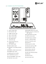
 use the micro switch with the same name on the rear panel 

of the unit (

see section 9. DIAGRAM and LIST OF FUNCTIONS

). When activated, if there 

is no audio signal in any of the inputs (or the signal is very weak, below the activation 
threshold), the CA120 automatically goes into STANDBY mode, and the 

ON/STBY

 on 

the front panel of the device goes orange. When a valid audio signal is detected in any 
of the inputs, the CA120 leaves standby mode and starts operating normally again and 
the 

ON/STBY

 LED goes green. 

When you enable 

AUTO STANDBY

 mode with the micro switch (position 

ON

) one of two 

things happens: 

o


There is NO audio signal in the inputs. Result: the amplifier immediately goes 
into AUTO STANDBY mode 

o


There is an audio signal in the inputs. Result: the amplifier stays active 
 

When the amplifier goes into 

AUTO STANDBY

 mode, all the LED indicators go out with 

the  exception  of 

ON/STBY

.  If  the  amplifier  is  in  STANDBY  mode  and  you  turn  the 

VOL/MUTE

 knob to adjust the volume or activate the MUTE function, the LED lights will 

come  on  for  a  short  time  then  go  out  again.  Remember  that  the  first  acting  on  the 
VOL/MUTE knob, this will only reset the LED indicators, and will not change any of the 
settings. 

When  the  unit  is  a  special  mode  (source  selection  or  setting  adjustment)  the  LED 
indicators will not go out even if the amplifier is in 

AUTO STANDBY 

mode. 


Summary of Contents for CA120

Page 1: ...50 0269 0104 CA120 EN v 20220510 CA120 AMPLIFIER Compact Amplifier USER MANUAL...

Page 2: ...4 Audio output connections 9 6 5 Remote control options 9 OPERATION AND USAGE 11 7 1 Start up and default mode 11 7 2 Special active source selection mode and setting adjustments 11 7 3 AUTO STANDBY F...

Page 3: ...k of electric shock The external wiring connected to the terminals requires installation by an instructed person or the use of ready made leads or cords WARNING To prevent fire or shock hazard do not...

Page 4: ...one by unplugging the power cable from the mains input socket For this reason it always shall remain easily accessible 15 Equipment is connected to a socket outlet with earthing connection by means of...

Page 5: ...year warranty COMPLIANCE WITH INTERNATIONAL STANDARDS The CA120 micro amplifier complies with the following international standards EN55103 1 Electromagnetic Compatibility Product family standard for...

Page 6: ...formance amplifier fan free convection cooling Suitable for stereo and parallel mono 1 switchable balanced mic unbalanced line input with high quality microphone preamplifier phantom power supply nois...

Page 7: ...le shelf cupboard etc thanks to its design and layout of its connectors controls and LED indicator lights 6 2 Mains connection The amplifier is powered by alternating current through its external powe...

Page 8: ...eamp The CA120 has the following operating modes according to the input sources selected as active LINE1 only LINE1 input is sent to the mix bus to be amplified and delivered to the L and R OUT output...

Page 9: ...REMOTE port the RJ 45 REMOTE type connector allows the connection of a WPmVOL or WPmVOL SR control 0 10 VDC wall control panel to adjust the general output volume and or to select one of the five act...

Page 10: ...ation on the connection and syntax of the commands supported The connection has the following specifications o Baud rate 9600 fixed without auto negotiation o Data bits 8 o Parity None o Stop bits 1 o...

Page 11: ...is turned to the left or to the right this flashes while the output volume increases or decreases The light stops flashing when it reaches either end of the scale and it is no longer possible to incr...

Page 12: ...is in special mode for 10 seconds and the front knob is not touched the equipment automatically reverts to VOL MUTE mode 2 In tone control mode when you turn the knob in either direction it flashes fa...

Page 13: ...0 leaves standby mode and starts operating normally again and the ON STBY LED goes green When you enable AUTO STANDBY mode with the micro switch position ON one of two things happens o There is NO aud...

Page 14: ...n mode being muted to return to normal operation in a short time MUTE This light up when the MUTE function is active silent mode ON STBY the green light comes on when the equipment is in normal operat...

Page 15: ...onsumption mode in the absence of audio signals in its inputs STEREO MONO ST MONO Select the work mode of the amplified outputs of the unit o ST Work in stereo mode L R o MONO Work in MONO mode both c...

Page 16: ...ext time you turn it on the factory settings will be in the memory Note for instructions on how to update the unit s firmware see the product web page at www ecler com where you will find the update s...

Page 17: ...eiver 13 REMOTE micro switch 14 NOISE GATE micro switch 15 TALKOVER micro switch 16 AUTO STANDBY micro switch 17 MIC LIN3 micro switch 18 STEREO MONO micro switch 19 Remote control by protocol CA NET...

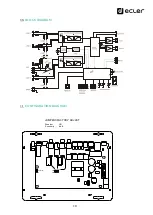
Page 18: ...18 BLOCK DIAGRAM CONFIGURATION DIAGRAM 6dB 0dB Sensitivity Phantom on off Sensitivity 6dB Phantom ON JUMPERS FACTORY ADJUST...

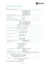
Page 19: ...TROL LINE MIC BASS 100Hz 10dB TREBLE 6KHz 10dB SIGNAL NOISE RATIO LINE 85dB MIC BAL 65Db TALKOVER TIME 2 Sec DEPTH 30dB MICROPHONE NOISE GATE 20 30 below max PHANTOM VOLTAGE 24VDC 10mA max RS 232 BAUD...

Page 20: ...ht to make changes or improvements in the design or manufacturing that may affect these product specifications For technical queries contact your supplier distributor or complete the contact form on o...

Reviews: