background image


8

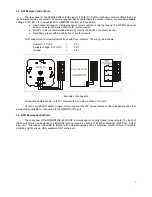
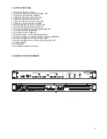
3.10. Front panel controls and LED indicators 


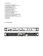
The following elements are available on the MIMO88 front panel: 


• 

MONITOR output (1) (marked with a headphones symbol): it produces the same monitoring signal already 
available via the rear panel screw terminal block, but here on a ¼" TRS jack and with a rotary volume 
control (2 ) for listening through headphones. It is especially useful for listening to input or output signals 
without disturbing the normal operation. In 16x16 mode both MIMO units receive the same signal. The 
monitored signal is selected with EclerNet Manager control software. Please refer to the EclerNet Manager 
software manual for more information. 

• 

Input LED indicators (3): indicate the presence of audio signal at the unit’s input, and its intensity level 
(green, amber and red indicate in this order the increased intensity level) 

• 

Output LED indicators (4): indicate the presence of audio signal at the unit’s output, and its intensity level 
(green, amber and red indicate in this order the increased intensity level) 

• 

Status LED indicators (STATUS): 

DATA: (5) Off: there is no connection to EclerNet Manager even if connected to Ethernet. On: 
connected to EclerNet Manager or to other third party application via TP-NET protocol. Flashing: 
data traffic with EclerNet Manager or another application. 

LINK: (6) 

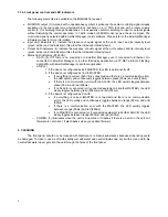
1. If the device is configured as 8x8 MASTER, the LED is permanently off. 
2. If the device is configured as 16x16 MASTER: 

• 

If everything is correct (SLAVE is connected and there is no communication error), 
the LED quickly and continuously toggles between green (50ms) and unlit (50ms) 

• 

If there is a communication error with the SLAVE, the LED quickly toggles between 
green (50ms) and red (200ms) 

• 

If no SLAVE is connected (or if connected equipment is another MASTER), the LED 
slowly toggles between green (800ms) and red (200ms) 

3. If the device is configured as SLAVE: 

• 

If everything is correct (MASTER is connected and there is no communication 
error), the LED quickly and continuously toggles between orange (50ms) and unlit 
(50ms) 

• 

If there is a communication error with the MASTER, the LED quickly toggles 
between orange (50ms) and red (200ms) 

• 

If no MASTER is connected (or if connected equipment is another SLAVE), the LED 
slowly toggles between orange (800ms) and red (200ms) 

POWER: (7) illuminates when the unit is in operation. It flashes if there is an error in the unit or if 
firmware is not correct. It also flashes when you update firmware 


4. CLEANING 


The front panel should not be cleaned with dissolvent or abrasive substances because silk-printing could 

be damaged. To clean it, use a soft cloth slightly wet with water and neutral liquid soap; dry it with a clean cloth. Be 
careful that water never gets into the unit through the holes of the front panel. 

Summary of Contents for MIN088

Page 1: ...USER MANUAL MANUAL DE INSTRUCCIONES NOTICE D UTILISATION BEDIENUNGSANLEITUNG...

Page 2: ......

Page 3: ...rol 06 3 6 LINK BUS digital audio port 06 3 7 REMOTE ports 1 and 2 for digital remote controls 06 3 8 GPI Remote Control Ports 07 3 9 GPO Remote Control Ports 07 3 10 Front panel controls and LED indi...

Page 4: ...ance 8 GPI control ports General Purpose Input 8 GPO control ports General Purpose Output Programming and remote management via Ethernet using EclerNet Manager or point to point with a direct CAT5 cab...

Page 5: ...s On the rear panel there is a power switch for the unit 19 next to the IEC power connector On the front panel a LED 7 lights up when the unit is switched on The mains cables must not be near the shie...

Page 6: ...MASTER SLAVE pair is done with EclerNet Manager application and communication uses the Ethernet port of the MASTER unit only it s not necessary to use the Ethernet port of the SLAVE unit Except for up...

Page 7: ...onnectors are screw terminal blocks with three contacts The wiring is as follows Positive 10 VDC Pin Variable voltage 0 10 VDC Pin Ground Pin Examples of connection Connecting cables can be up to 500...

Page 8: ...ager or another application o LINK 6 1 If the device is configured as 8x8 MASTER the LED is permanently off 2 If the device is configured as 16x16 MASTER If everything is correct SLAVE is connected an...

Page 9: ...Power on indicator POWER 8 Signal output screw terminal OUT 9 Signal input screw terminal IN 10 Signal output screw terminal MONITOR 11 RJ 45 connector ETHERNET 12 RJ 45 connector LINK BUS 13 MASTER...

Page 10: ...gital 13 3 7 Puertos REMOTE 1 y 2 para controles remotos digitales 13 3 8 Puertos GPI de control remoto 14 3 9 Puertos GPO de control remoto 14 3 10 Controles e indicadores LED del panel frontal 15 4...

Page 11: ...urpose Input 8 puertos de control GPO General Purpose Output Programaci n y gesti n remota v a Ethernet mediante aplicaci n EclerNet Manager bien punto a punto con cable CAT5 directo bien desde un pue...

Page 12: ...ptor de encendido apagado de la unidad 19 En el panel frontal existe un indicador LED 7 que se ilumina cuando al unidad se encuentra en funcionamiento Debe evitarse que el cable de red se entremezcle...

Page 13: ...eciendo comunicaci n nicamente mediante el puerto Ethernet de la unidad MASTER no siendo preciso emplear el puerto Ethernet de la unidad SLAVE Excepto para actualizar el firmware Precauci n el enlace...

Page 14: ...de tres contactos La asignaci n del conexionado es la siguiente Positivo 10 VDC Terminal Tensi n variable 0 10 VDC Terminal Masa Terminal Algunos ejemplos de conexionado Los cables de conexi n pueden...

Page 15: ...rotocolo TP NET Parpadea tr fico de datos con el EclerNet Manager u otros o LINK 6 1 Si el dispositivo est configurado como MASTER 8x8 el LED permanece apagado 2 Si el dispositivo est configurado como...

Page 16: ...marcha POWER 8 Terminales atornillables salida de se al OUT 9 Terminales atornillables entrada de se al IN 10 Terminales atornillables salida de se al MONITOR 11 Conector RJ 45 ETHERNET 12 Conector R...

Page 17: ...grammation et la commande 20 3 6 Port LINK BUS de liaison audio num rique 20 3 7 Ports REMOTE 1 et 2 pour t l commandes num riques 20 3 8 Ports GPI de t l commande 21 3 9 Ports GPO de t l commande 21...

Page 18: ...e de commande GPO General Purpose Output Programmation et gestion distance via Ethernet au moyen de l application EclerNet Manager ou point point avec un c ble CAT5 direct ou depuis un poste de r seau...

Page 19: ...e et c t du connecteur d alimentation IEC se trouve un interrupteur marche arr t de l unit 19 Sur la face avant un voyant LED 7 s allume lorsque l appareil est en service viter de m ler les cordons se...

Page 20: ...LAVE se font au moyen de l application EclerNet Manager et la communication uniquement au travers du port Ethernet de l unit MASTER il n est pas n cessaire d utiliser le port Ethernet de l unit SLAVE...

Page 21: ...PI sont de type borniers vissables L assignation des connecteurs est la suivante Positif CC 10 V Borne Tension variable CC 0 10 V Borne Masse Borne Exemples de connexion Les c bles de connexion peuven...

Page 22: ...s avec l application EclerNet Manager ou d autres o LINK liaison 6 1 Si l appareil est configur comme ma tre MASTER 8x8 la LED reste teinte 2 Si l appareil est configur comme ma tre MASTER 16x16 Si to...

Page 23: ...ers vissables de sortie de signal OUT 9 Borniers vissables d entr e de signal IN 10 Borniers vissables de sortie de signal MONITOR 11 Connecteur RJ 45 ETHERNET 12 Connecteur RJ 45 LINK BUS 13 S lecteu...

Page 24: ...Verbindungsport f r digitale Audiotechnik 27 3 7 REMOTE Ports 1 und 2 f r digitale Fernsteuerung 27 3 8 GPI Ports f r Fernsteuerung 28 3 9 GPO Ports f r Fernsteuerung 28 3 10 Bedienelemente und LED An...

Page 25: ...rnung 8 GPI Kontrolleing nge General Purpose Input 8 GPI Kontrollausg nge General Purpose Output Fernsteuerung und programmierung ber Ethernet mit EclerNet Manager von Punkt zu Punkt mit direktem Cat...

Page 26: ...m IEC Anschluss der Schalter zum Ein und Ausschalten des Ger ts 19 An der Vorderseite befindet sich eine LED Anzeige 7 die aufleuchtet wenn das Ger t eingeschaltet ist Das Netzkabel darf nicht in der...

Page 27: ...ikation EclerNet Manager wobei die Verbindung nur ber den Ethernetport des MASTER Ger ts hergestellt wird Der Ethernetport des SLAVE Ger ts wird nicht ben tigt Mit Ausnahme von Firmware Updates Vorsic...

Page 28: ...ef hrt Die Anschl sse sind wie folgt zugewiesen Positiv 10 VDC Anschluss Variable Spannung 0 10 VDC Anschluss Masse Anschluss Einige Beispiele f r Anschlussm glichkeiten Die Anschlusskabel k nnen bis...

Page 29: ...zeige blinkt Datenverkehr mit dem EclerNet Manager oder mit sonstigen Anwendungen o LINK 6 1 Wenn das Ger t als 8x8 MASTER konfiguriert wurde bleibt die LED Anzeige aus 2 Wenn das Ger t als 16x16 MAST...

Page 30: ...triebsetzung POWER 8 Schraubbare Klemmleiste Signalausgang OUT 9 Schraubbare Klemmleiste Signaleingang IN 10 Schraubbare Klemmleiste Signalausgang MONITOR 11 RJ45 Buchse ETHERNET 12 RJ45 Buchse LINK B...

Page 31: ...ated Jack Analog Input headroom 27dBV 30dBu Max output level 18dBV 21dBu Input sensitivity 0dBV out From 50dBV to 10dBV in 0 5dB step Input Impedance Balanced 4k Phantom power 42VDC 5mA max software s...

Page 32: ...Pass 6 12 dB oct All Pass 1 2 order High Low pass output Crossover filters x8 Bypass On Off Butterworth in 6 12 18 24 dB oct Bessel in 12 18 24 dB oct Linkwitz Riley in 12 24 dB oct Input Noise Gate...

Page 33: ...ol Input Output Crosspoint Mute Set Clear individual row column all Input output Mono stereo selector Meter Input output VU and clip Pager x2 Input IN1 to IN8 or to IN16 in 16x16 Priorities 1 max 2 mi...

Page 34: ...rols thru Ethernet with interactive graphical display Grouping mode channels or devices Grouping of other groups Automated report generation Up to 256 devices on same net Autodiscovery devices feature...

Page 35: ...35 8 BLOCK DIAGRAM 8 DIAGRAMA DE BLOQUES 8 DIAGRAMME DE BLOCS 8 BLOCKSCHATBILD...

Page 36: ...ECLER Laboratorio de electro ac stica S A Motors 166 168 08038 Barcelona Spain INTERNET http www ecler com E mail info ecler es 50 0215 01 00...

Reviews: