background image

v.20200302 


WiSpeak Hardware 

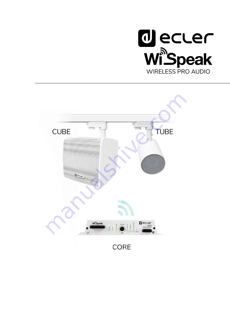
WiSpeak 

 Wireless Pro Audio 

Transmitters - Receivers 


USER MANUAL 


Summary of Contents for WiSpeak

Page 1: ...v 20200302 WiSpeak Hardware WiSpeak Wireless Pro Audio Transmitters Receivers USER MANUAL ...

Page 2: ...receivers mounting and power up 13 6 3 CORE transmitter installation 16 7 PAIRING THE RECEIVERS STARTING UP THE WiSpeak SYSTEM 18 8 CORE transmitter VOLUME control REMOTE and MUTE control ports 20 9 LED information codes and additional procedures 21 9 1 CORE transmitter 21 9 2 TUBE CUBE receivers 23 9 2 1 TUBE 23 9 2 2 CUBE 24 10 Extended information about the WiSpeak PAIRING PROCEDURE 25 11 UNPAI...

Page 3: ...3 14 FUNCTION DIAGRAMS 28 14 1 CORE 28 14 2 TUBE 29 14 3 CUBE 30 15 TECHNICAL CHARACTERISTICS 31 15 1 CORE 31 15 2 TUBE 33 15 3 CUBE 35 ...

Page 4: ...rked with symbol of may be of sufficient magnitude to constitute a risk of electric shock The external wiring connected to the terminals requires installation by an instructed person or the use of ready made leads or cords WARNING To prevent fire or shock hazard do not expose this equipment to rain or moisture WARNING An apparatus with Class I construction shall be connected to a mains socket outl...

Page 5: ...ifier will be stopped but fully disconnecting the device from mains is done unplugging the power cord from the mains input socket For this reason it always shall remain readily operable 15 Equipment is connected to a socket outlet with earthing connection by means of a power cord 16 The marking information is located at the bottom of apparatus 17 The apparatus shall not be exposed to dripping or s...

Page 6: ... with or without the use of the WiSpeak grip app Plug play no wires no construction works The receivers just need to get mains AC usually from the already existing lighting rails They integrate an internal universal Power Supply 100 240VAC 50 60Hz Solid and stable wireless transmission protocol robust against audio drops Up to 500 m2 coverage depending on the location of the transmitter and the re...

Page 7: ...nder the control of the Master unit The Master unit has these main functions to pair link and keep a stable communication with all the receiver units in the system when paired and within the valid wireless coverage range supervising the connection quality of them all to take care of the global configuration of the system audio inputs in use equalisation levels etc to send the individual configurat...

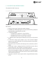
Page 8: ...AUX OUT analogue signal available a copy of the transmitted WiSpeak signal It can be used for linking the unit to external audio devices like amplifiers mixers or subwoofer units MUTE port to allow the system s audio silencing when an external dry contact is closed REMOTE port to allow a simple general volume control for the end user within a programmable range using a WPaVOL or compatible wall pa...

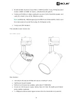
Page 9: ...le for Android and iOS can be used for an advanced set up and fine tuning of a WiSpeak system Front panel LED indicators The available receiver devices are 5 2 TUBE model Main features Lamp style self powered WiSpeak receiver including 3 driver Lighting rail mount included Surface mount accessory available optional ref TUBE SMA Universal internal power supply taking mains AC from the lighting rail...

Page 10: ...tweeter drivers Lighting rail mount included Surface wall mount accessory included Universal internal power supply taking mains AC from the lighting rail bracket 100 240VAC 50 60Hz or from the external AC wire both included 1 x WiSpeak wireless audio signal received from the transmitter it is paired to 1 x AUX OUT analogue signal available a copy of the received WiSpeak signal It can be used for l...

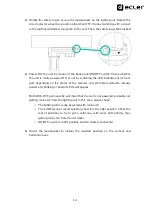
Page 11: ...unted Follow these steps to install a TUBE unit in a lighting rail 1 Ensure that the 4 position OFF 1 2 3 circuit selector wheel in the TUBE unit is in the OFF position 2 Insert the loudspeaker in the lighting rail as shown in the image Connection to a GLOBAL Trac Pro Eutrac lighting rail three circuit lighting track system ...

Page 12: ...t is not powered probably not getting mains AC from the lighting rail In this case please check o The lighting rail is really powered with mains AC o The TUBE receiver circuit selector wheel is in the right position Check the rest of positions to try to get a valid one with some LED activity thus getting mains AC from the rail tracks 5 Orient the loudspeaker to obtain the required position on the ...

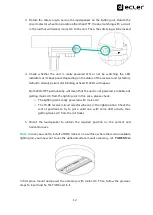
Page 13: ...the rail mount or the wall mount included brackets To do so the supplied self adhesive rubber legs can be attached to the unit s bottom face and the connection to a standard AC plug can be performed using the supplied additional AC cord Follow these steps to install a CUBE unit in a lighting rail 1 Ensure that the 4 position OFF 1 2 3 circuit selector wheel in the CUBE unit is in the OFF position ...

Page 14: ...tus of the receiver unit at factory defaults already paired etc blinking or fixed lit LEDs will appear Both LEDs OFF permanently will mean that the unit is not powered probably not getting mains AC from the lighting rail In this case please check o The lighting rail is really powered with mains AC o The CUBE receiver circuit selector wheel is in the right position Check the rest of positions to tr...

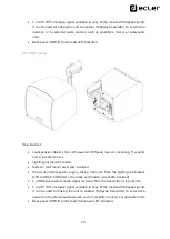
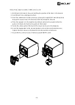
Page 15: ... hole in the bracket Attach the bracket to the wall 4 Place the speaker in its final position by sliding it vertically downward so that the guide on its back side matches the guide on the bracket 5 Fasten the safety guide at the back of the mount as shown in the diagram 6 Orient the loudspeaker to the desired position on the vertical and horizontal axes Tighten the Allen screws on the bracket to f...

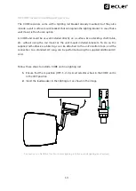
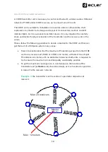
Page 16: ...follow the following guidelines to decide a location for the CORE unit that can get the best of a WiSpeak system in any venue Take into consideration that the maximum RF operating scope from the CORE unit to any receiver unit TUBE or CUBE is 12 meters with direct line of sight This distance or shorter with no obstacles in between both units is required to try to ensure the maximum connection quali...

Page 17: ...f the maximum coverage area in the first example Once decided its location the CORE transmitter must be fed with up to 3 audio inputs INPUT 1 stereo balanced Euroblock connectors rear panel INPUT 2 stereo unbalanced RCA connectors rear panel INPUT 3 stereo received via Bluetooth class 1 up to 25 metre range front panel antenna Max 24 receivers Master Máx 12 meters transmitter ...

Page 18: ...s etc By default this output will deliver exactly the same audio signal as the one sent to the receivers network but this can be modified using the WiSpeak grip app When all the connections are made it s time to power up the transmitter using the included external power supply connected to the DC IN terminal at the rear panel and start the WiSpeak setup process 7 PAIRING THE RECEIVERS STARTING UP ...

Page 19: ... input is selected its blue LED will remain permanently lit when there s a Bluetooth emitter paired and correctly connected to it and will blink when there is not Gesture the VOLUME knob to adjust the Master general volume of the installation A short press of the same knob will activate deactivate the MUTE function of the system meanwhile MUTE is ON Volume can t be modified Note the Bluetooth audi...

Page 20: ...back panel of a CORE transmitter provides these 3 volume control options LOCAL APP at this switch position the general volume of the WiSpeak system can be controlled using the front panel VOLUME knob and the WiSpeak grip app Both methods can adjust the volume within the minimum and maximum volume range that can be defined using the WiSpeak grip app Admin user The REMOTE VOLUME port is disabled in ...

Page 21: ... permanently The unit is paired to a network of receivers and working properly with all the paired receivers currently online This is the usual status after the system has been set up and running in normal conditions with no receiver in offline condition ON Blinking sequence 3 seconds loop Within a 3 seconds loop sequence every single blink that is shown means that one of the paired receivers is o...

Page 22: ...rt press on SELECT key will exit the gain adjust mode BLUETOOTH LED o Permanently ON the Bluetooth input is selected and there is an external device smartphone tablet computer audio player etc connected to the CORE unit for audio transmission A2DP If a valid media is played in this external device and transmitted via Bluetooth it will be received by the CORE unit and sent via WiSpeak wireless audi...

Page 23: ...iver status OFF ON permanently The unit is paired with a transmitter currently reached by it online and receiving WiSpeak wireless audio correctly This is considered the correct status of a receiver in normal working conditions OFF Blinking The unit is paired with a transmitter but currently not online with it for any reason the transmitter is OFF out of range etc and trying to establish a proper ...

Page 24: ...manently The unit is paired with a transmitter currently reached by it online and receiving WiSpeak wireless audio correctly This is considered the correct status of a receiver in normal working conditions OFF Blinking The unit is paired with a transmitter but currently not online with it for any reason the transmitter is OFF out of range etc and trying to establish a proper WiSpeak connection Bli...

Page 25: ...takes to finish it It ends up with a internal list in the transmitter containing the successfully paired receivers When performed over again for the second third time or further it scans once more to check whether those receivers already in the paired list are online or not and also tries to find out more available new unpaired receivers The list is then increased including the new receivers succe...

Page 26: ...mation Press and hold the WiS PAIR recessed key with a small screwdriver or pin tool for more than 5 seconds WiS and RX LEDs will start blinking alternately for some seconds until the unpair process finishes After a successful unpair procedure WiS LED should remain lit ON and the RX LED should blink quickly in the transmitter meaning this that the transmitter unit is ready to be paired to a networ...

Page 27: ...thout the proper permissions and or without the right knowledge of their consequences we beg you ask your official WiSpeak installer distributor to carry them out 13 CLEANING The casing should not be cleaned with solvents or abrasive materials since they can damage the screen printing To clean the product please used a cloth dampened with a mild liquid detergent and water and wipe it off with a dr...

Page 28: ...nput 1 LED 7 Input 2 LED 8 Bluetooth LED 9 Input Source Selector 10 Bluetooth Antenna 11 Service USB C port 12 Volume Remote RJ45 Port 13 Volume Control Selector 14 Local Aux Output 15 Input 2 unbalanced RCA connector 16 Input 1 balanced Euroblock connector 17 Mute GPI 18 DC in 19 DC cable security fixation ...

Page 29: ...29 14 2 TUBE 1 WiSpeak interface status LED 2 WiSpeak Pair key 3 Wireless streaming reception status LED 4 Local Aux Output ...

Page 30: ...30 14 3 CUBE 1 WiSpeak interface status LED 2 Wireless streaming reception status LED 3 WiSpeak Pair key 4 Local Aux Output 5 Rail wall bracket guide 6 AC cable connector 7 Mains switch ...

Page 31: ...t TX AUX OUT IN1 10Hz 20kHz 1dB IN2 10Hz 20kHz 1dB BT 10Hz 20kHz 1dB THD D at TX AUX OUT IN 1 2 0 015 Signal Noise Ratio at TX AUX OUT IN 1 2 95dB Local Output Type AUX OUT Analog Mono Balanced Euroblock Input Selection CH 1 2 WiSpeak grip control app Nominal Output Level Min Load AUX OUT 0dBV 10kΩ WiSpeak Channels RF Wireless Audio Channel CH 1 2 Digital Mono RF Wireless Audio General Controls af...

Page 32: ...delay error 1us Reconnection time Up to 120s5 Pairing time Up to 120s5 Latency From TX Analog Audio IN to TX AUX OUT 700usec From TX Analog Audio IN to TR AUX OUT 6ms From TX Analog Audio IN to RX Speaker 6ms DSP Processor 25 56 bits Sampling Rate 48kHz Converters Resolution ADC DAC 24 bits Dynamic Range ADC 96dB DAC 98dB Miscellaneous Control Port USB C Service Firmware updates Supply DC Supply 2...

Page 33: ...io at RX AUX OUT 95dB Internal Loudspeaker Size 3 driver Impedance 4Ω Ways 1 Sensitivity 1W 1m 83dB Frequency range 105 20kHz 10dB Power Amplifier Power 4Ω 1 THD 18W THD N 1kHz Full Power 0 15 RF Wireless Audio Frequency band U NII 5 1 5 8GHz supported worldwide Up to 24 non overlapping RF channels2 DFS support Transmission Recommended Distance Up to 12m from a TX to any paired RX direct line of s...

Page 34: ...e 20Hz 20kHz 0 1dB Converters Resolution DAC 24 bits Dynamic range DAC 100dB Supply Mains voltage 100 240VAC 50 60Hz Rated power consumption 15W Power consumption pink noise 1 8 power 7W Power consumption pink noise 1 3 power 13W Mechanical Finish colour White RAL 9003 or black RAL 9005 Dimensions without arm 96mmx110mm 3 8 x4 3 Support arm Swivel pan and tilt Weight 0 8kg 1 76lb ...

Page 35: ...at RX AUX OUT 95dB Internal Loudspeaker Size 5 woofer 1 tweeter Impedance 8Ω Ways 2 Sensitivity 1W 1m 83dB Frequency response 70 20kHz Power Amplifier Power 8Ω 1 THD 32W THD N 1kHz Full Power 0 15 RF Wireless Audio Frequency band U NII 5 1 5 8GHz supported worldwide Up to 24 non overlapping RF channels2 DFS support Transmission Recommended Distance Up to 12m from a TX to any paired RX direct line ...

Page 36: ...0kHz 0 1dB Converters Resolution DAC 24 bits Dynamic range DAC 100dB Supply Mains voltage 100 240VAC 50 60Hz Rated power consumption 15W Power consumption pink noise 1 8 power 7 5W Power consumption pink noise 1 3 power 14W Mechanical Finish colour White RAL 9003 or black RAL 9005 Dimensions without arm WxHxD 175x175x180mm 6 9 x6 9 x7 1 Support arm Swivel pan and tilt Weight 2 1 kg 4 6lb ...

Page 37: ...to production tolerances NEEC AUDIO BARCELONA S L reserves the right to make changes or improvements in the design or manufacturing that may affect these product specifications Motors 166 168 08038 Barcelona Spain 34 932238403 information ecler com www ecler com ...

Reviews: