18
Note:
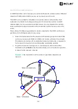
INPUT 3 (Bluetooth®, class 1) and, especially, INPUT 1 (analogue, balanced)
are suitable options to use when the transmitter unit is tried to be located as much
centred as possible in respect to the loudspeakers (for instance, on the ceiling of a
retail store, a restaurant or a corporate room), with the aim to get the maximum
coverage are possible. Both options allow sending audio from the music source
(audio player) to the transmitter over long distances, which would be necessary in
some cases, where it’s not possible to have booth devices close to each other.
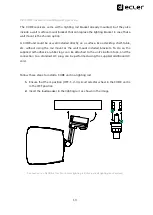
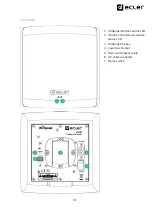
For each channel (left or right) of the balanced input, INPUT1, the wiring is as follows):
Hot or direct signal
>
+ terminal
Cold or inverted signal
>
–
terminal
Ground
>
⊥
terminal
The AUX OUT connection is available to connect external audio systems, like subwoofer
reinforcement loudspeakers, mixers, amplifiers, matrices, etc. By default, this output will
deliver exactly the same audio signal as the one sent to the
receivers’
network, but this
can be modified using the WiSpeak grip app.
When all the connections are made, it’s time to power up the transmitter using the
included external power supply, connected to the DC IN terminal at the rear panel, and
start the WiSpeak setup process.
7.
PAIRING THE RECEIVERS & STARTING UP THE WiSpeak SYSTEM
When a CORE transmitter is powered up for the very first time (or after a Factory
Defaults reset has been applied to it), it will show the
WiS
LED permanently lit ON and
the
RX
LED quickly blinking.
This LED code means that the CORE unit is ready to be paired to a network of receivers,
TUBE and/or CUBE models, up to a maximum of 24 of them.
Note:
bef
ore stating a pairing procedure, it’s extremely important to check that
the CORE transmitter and every single TUBE or CUBE receiver are them all
powered ON and within the coverage range of the WiSpeak system. Otherwise,
a
Partial Pairing
result can be achieved (See chapter 9 for further information)


