Appendices
24
A
CONNECTOR TYPES AND PIN DEFINITIONS
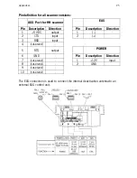
This unit
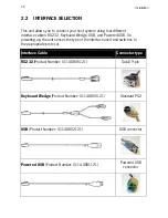
supports triple interface in one standard unit: RS232, Keyboard
Wedge (KBW) and USB/USB plus power. The various pin definitions for the
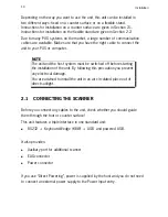
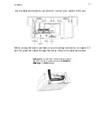
applicable Data port are given on page 20 and 21. The connector to be
used for the port is indicated below.
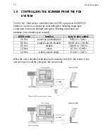
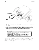
To activate USB or KBW interface, follow this sequence:
1.
Plug in the appropriate interface cable and then power up the
unit
.
2.
Scan the following codes from the Configuration Guide:
-
Open
the
unit
Programming Mode by scanning code 1.1
-
Return
to factory default settings by scanning code 1.3
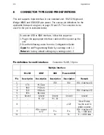
Pin definitions for multi interface:
Connector: RJ-48, 10 pins
Multiple Interface
RS-232 KBW
USB
Powered
USB
Pin Description Description Description Description
Remark
1
-
-
IFID
IFID
IFID = Interface ID
2
CTS
PC-Clock
-
-
-
3
RxD
PC-Data
-
-
-
4
TxD
KB-Data
-
-
IFID = Interface ID
5
RTS
KB-Clock
-
-
-
6 Ground Ground Ground
Ground
Ground
7
-
PC - 5V
PC - 5V
-
-
8
-
-
-
+12V
Direct Power,
may be used to
power scanner
9
-
IFID: connect
to ‘6’
D
+
D
+
IFID = Interface ID
D
+
= USB data
10
-
-
D
-
D
-
D
-
= USB data
Summary of Contents for EC-OS-7200D
Page 1: ......
Page 2: ...User s Manual...
Page 6: ...Chaper 1 Product Overview...
Page 16: ......
Page 17: ...Chapter 2 Installation...
Page 27: ...Appendices A Connector types and pin definitions B Technical Specifications C Troubleshooting...
Page 30: ...Appendices 26...
Page 36: ......


