Appendices
25
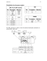
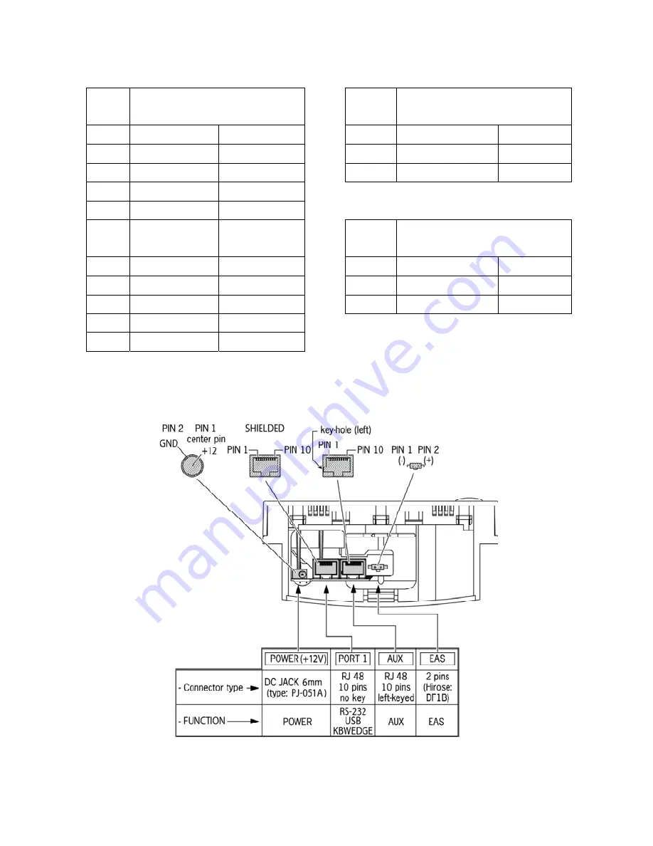
Pin definition for all scanner versions:
AUX Port for HH scanner
EAS
Pin Description
Direction
Pin Description Direction
1
+5 VDC
output
1
( - )
-
2 CTS input
2
(+)
-
3 RXD input
4 (reserved)
-
5 RTS output
POWER
6 GND
-
Pin Description
Direction
7 (reserved)
-
1
+12V
input
8 (reserved)
-
2
GND
9 (reserved)
-
10 (reserved)
-
The EAS connection is used to connect the internal deactivation antenna to an
external EAS control unit.
Summary of Contents for EC-OS-7200D
Page 1: ......
Page 2: ...User s Manual...
Page 6: ...Chaper 1 Product Overview...
Page 16: ......
Page 17: ...Chapter 2 Installation...
Page 27: ...Appendices A Connector types and pin definitions B Technical Specifications C Troubleshooting...
Page 30: ...Appendices 26...
Page 36: ......

