9
Eclipse AirHeat Burner, V2, Design Guide 135, 6/16/2010
Step 4: Ignition System
Ignition Transformer
For the ignition system, use a transformer with:
• secondary voltage 6000 to 8000 VAC
• minimum secondary current 0.02 amp continuous
• full wave output
DO NOT USE
the following:
• twin outlet transformer
• distributor type transformer
Trial For Ignition
It is recommended that low fire start be used. However,
under certain circumstances AirHeat burners are capable
of direct spark ignition at higher gas inputs.
Most local safety codes and insurance requirements limit
the maximum trial for ignition time (the time it takes for a
burner to ignite). These requirements vary from one
location to another; check your local codes and comply to
the strictest codes applicable.
The time it takes for a burner to ignite depends on the
following:
• the distance between the gas shut-off valve and the
burner.
• the gas flow conditions at start-up.
The possibility exists where the low fire is too low to ignite
the burner within the maximum trial for ignition time. The
following options must be considered under these
conditions:
• start at higher gas input levels.
• resize and/or relocate the gas controls.
• use spark ignited pilot.
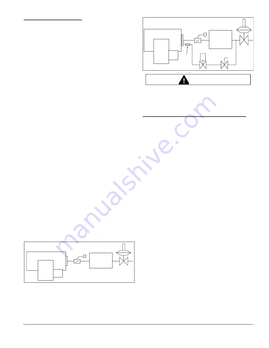
Ignition Gas Piping
AirHeat burners are capable of ignition with either direct
spark or spark ignited pilot.
Direct Spark Ignition
Spark Ignited Pilot
When ordered, the pilot is packaged with the burner and
includes an adjustable flow gas cock and pressure
regulator.
Ŷ
It is not possible to use a continuous or
intermittent pilot. The pilot fuel flow should be
interrupted after the trial ignition period has
expired.
Step 5: Flame Monitoring Control System
The flame monitoring control system consists of two main
components:
• flame sensor
• flame monitoring control
Flame Sensor
Two types can be used on AirHeat Burners:
• flame rod
• UV scanner
The UV scanner must be compatible to the flame
monitoring control that is used. Refer to the manual of
your selected control for proper selection of the scanner.
Flame Monitoring Control
The flame monitoring control processes the signal from
the flame sensor and controls the start-up and shut-down
sequences.
Eclipse recommends the following flame monitoring
controls:
• Trilogy series T400 (Instruction Manual 830)
• Veri-Flame series 5600 (Instruction Manual 818)
• Bi-Flame series 6500 (Instruction Manual 826)
• Multi-Flame series 6000 (Instruction Manual 820)
If other controls are considered, contact Eclipse to
determine how burner performance may be affected.
Flame monitoring controls that have lower sensitivity
flame detecting circuits may limit burner turndown and
change the requirements for ignition.
Flame monitoring controls that stop the spark as soon as
a signal is detected may prevent establishment of flame,
particularly when using UV scanners. The flame
monitoring control must maintain the spark for a fixed time
interval that is long enough for ignition.
Main Gas
shut-off
valve train
NC
M
a
in G
a
s
S
hut-O
ff
Va
lve Tr
a
in
Pilot
CAUTION


