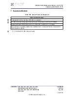
•
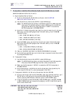
“DF17 DETECTED” = YES (IF ADS-B OUT IS INSTALLED) / NO (IF ADS-B
OUT IS NOT INSTALLED)
•
“FLT ID” = same as tail number
•
“AA” = ICAO code assigned to this aircraft/tail number (8 digit number in
parenthesis)
•
“FS” = IN-AIR
•
“VS” = IN-AIR
(11) On MFD, press SYS along bottom of MFD. Use the small lower knob on the MFD to
scroll to the SETUP page. On the SETUP page, press the SETTINGS softkey to
bring up the SETTINGS page. At the bottom of the SETTINGS page, verify:
(a) The “REGISTRATION NO” number (alphanumeric) matches the “TAIL” number
(alphanumeric) displayed on the IFR 6000 (above).
(b) The “ICAO 24-BIT (OCT)” number matches the “AA” ICAO 24-bit code displayed
on the IFR 6000 (above).
NOTE: If the aircraft’s registration number and/or ICAO 24-bit (octal) number are not
present on the MFD’s SETTINGS page, the Aircraft Configuration File must
be updated, refer to
AMM-31-40-00-051-801 – Aircraft Computer Systems -
Steps (10) through this step must then be repeated.
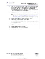
(12) On the MFD, scroll to the SETUP tab, press the SENSOR Soft Key. Set the ADC
PFD source selection from AUTO to ADC 2.
(13) On the IFR 6000, press the XPDR button once.
(14) Once XPDR – ALT ENCODER is displayed, press the SOURCE SELECT Soft Key
until SOURCE - XPDR is displayed. Press the RUN TEST Soft Key.
(15) Make sure that an altitude reported on IFR 6000 matches L PFD altitude indication
+/- 100 ft.
(16) On the MFD, set the ADC source back to AUTO.
(17) Set the WOW Box Switches to W-on-W (on-ground).
(18) Set D-XPDR 2 to STANDBY MODE.
D. Diversity Transponder-2 MODE A,C,S Test using Transponder Test Set (IFR 6000)
(Lower Antenna)
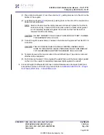
(1) Remove Antenna Clamp and Shield Assembly (part of Transponder Test Set IFR
6000) from lower transponder antenna (bottom center cabin/fuselage).
(2) Remove CU-584S Antenna Coupler from upper transponder antenna.
(3) Install Antenna Clamp and Shield Assembly (part of Transponder Test Set IFR 6000)
on upper transponder antenna (top of the center cabin/fuselage), in accordance with
instructions in IFR 6000 Ramp Test Set Operation Manual.
(4) Install CU-584 Antenna Coupler on lower transponder antenna. Refer to Job Set-Up
with UC-584 Antenna Couplers
SUBTASK AMM-34-50-20-071-921-001-A
.
(5) Remove Antenna Clamp and Shield Assembly (part of Transponder Test Set IFR
6000) from lower transponder antenna (bottom of the center cabin/fuselage).
EA500 Aircraft Maintenance Manual — 06-117751
Temporary Revision No. 34-21
EFFECTIVITY: 0001-0104, 0113-0115, 0120, 0123-0124
POST SB 500-99-002; AND 0105-0112,
0116-0119, 0121-0122, 0125-0262 PRE SB
500-99-005
34-50-20
CONFIG B
Page 516
Sep 30/20
© 2020 Eclipse Aerospace, Inc.

