4.
Procedure – Upper Over Fin Fairing – NOT INSTALLED –
SUBTASK AMM-34-40-50-071-B-701-001
A. Test Set-Up
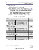
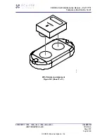
(1) Attach the WX-PA test set’s antenna to the LDS NY-163 antenna.
(a) Position the WX-PA antenna on the LDS antenna as shown in
.
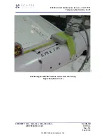
•
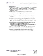
If necessary, use tape to secure WX-PA antenna; see
(b) Be sure to align the forwards arrows and position the WX-PA antenna suction
cups forward of center along the longitudinal axis.
(c) Attach antenna cable grounding clip to nearby structure to obtain a good ground.
See also
(2) Route the WX-PA antenna cable away from the aircraft.
(a) Connect the antenna cable to the WX-PA test box.
(b) DO NOT POWER UP THE TEST SET.
(3) On the IPL, set the SYS BATT and START BATT Switches to the ON (up) position
and BUS TIE to AUTO (up) position.
(a) Clear any “MASTER CAUTIONS” and “MASTER WARNINGS” as needed.
(b) On the MFD, press the PROCEED Line Select Key (LSK).
(4) Verify that no CAS messages are displayed indicating Lightning equipment failures.
(5) On the MFD ECB AVIONICS synoptic page, PULL the ECB:
•
ECB - LIGHTNING DETECT SYS (R AFT Bus)
(6) Verify that a LIGHTNING DETECT FAIL CAS message is displayed.
(7) On the MFD ECB AVIONICS synoptic page, reset the ECB:
•
ECB - LIGHTNING DETECT SYS (R AFT Bus)
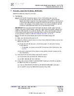
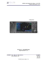
(8) On the PFD WXR tab select the CELL option for the Stormscope.
Refer to
(a) Verify that the Strike Rate is displayed on the PFDs (‘+’ shaped symbols may
also be displayed on the HSI, if lightning is present).
(9) Depress the right LSK #4 to set the Stormscope mode to STRIKE.
(a) Verify that the Strike Rate is displayed on the PFDs (‘x’ shaped symbols may
also be displayed on the HSI, if lightning is present).
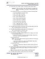
(10) On either PFD, tune the VHF 1 COMM radio to a test frequency (e.g., 123.450 MHz).
(a) Select COM 1 as the ACTIVE radio (if not already selected).
EA500 Aircraft Maintenance Manual — 06-117751
Temporary Revision No. 34-21
EFFECTIVITY: 0001 - 0008, 0010 - 0050, 0052, 0054 -
0267 POST SB 500-31-024
34-40-50
CONFIG B
Page 502
Sep 30/20
© 2020 Eclipse Aerospace, Inc.

