28
P0031-LI-02.01
6. Panel Outputs and Devices
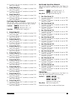
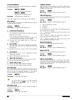
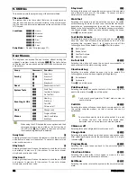
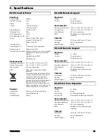
This section covers programming of the control panel outputs,
communication ports and other devices that maybe connected to
the control panel.
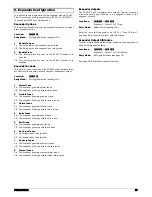
Panel Output Type
This set of options allows the output type (function) to be
assigned to the control panel high current outputs.
Locations:
6111
to
6114
Panel Outputs 1 to 4: Output Type.
Entry Mode:
Selection List (see page 15).
Enter the four digit type number, e.g., 0201 = “Control Timer 1”.
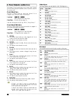
Panel Output Attributes
This set of options allows the output attributes to be assigned to
the control panel high current outputs.
Locations:
6121
to
6124
Panel Outputs 1 to 4: Output Attributes.
Entry Mode:
Bit Toggle Selection (see page 16).
1 Latching
On: The selected output latches on when triggered and is only
cleared when the user resets the system.
Off: The selected output responds normally.
2 Inverted
On: The selected output is inverted, off when active and on when
inactive.
Off: The selected output responds normally.
3 User
Test
On: The selected output is activated when the user output test is
selected.
Off: The selected output remains unchanged during the user
output test.
4 Pulse
1
On: The selected output activates for the duration of the “Pulse
1 Time” system timer, see page 23.
Off: The selected output responds normally.
5 Pulse
2
On: The selected output activates for the duration of the “Pulse
2 Time” system timer, see page 23.
Off: The selected output responds normally.
6 Delay
1
On: The selected output activates after the delay set by the
“Delay 1 Time” system timer, see page 23.
Off: The selected output responds normally.
7 Delay
2
On: The selected output activates after the delay set by the
“Delay 2 Time” system timer, see page 23.
Off: The selected output responds normally.
8 Armed
Only
On: The selected output only activates if the system is armed.
Off: The selected output responds normally.
If “Pulse 1” and “Pulse 2” options are enabled then the
selected output activates for the duration of the “Pulse
3 Time” system timer, see page 23.
If “Delay 1” and “Delay 2” options are enabled then the
selected output activates after the delay set by the
“Delay 3 Time” system timer, see page 23.
Output Types
The output types are grouped together in the following groups:
Group Description
00 Global
Global system output function.
01 Partition
Not available on the EC-P8.
02 Control
Timer
Control Timers 1 to 5.
03 Remote
Control
Remote control outputs 1 to 5.
04 Link
Control
Input linked logical conditioned outputs.
10 Zone
Count
Zones 1 to 18 count outputs.
20 Zone
Mimic
Zones 1 to 18 mimic outputs.
30 Zone
Alarm
Zones 1 to 18 alarm outputs.
40 Zone
Tamper
Zones 1 to 18 tamper alarm outputs.
50 Zone
Masked
Zones 1 to 18 masked outputs.
60 Zone
Fault
Zones 1 to 18 fault outputs.
70 Zone
Bypassed
Zones 1 to 18 bypassed outputs.
80 User
Access
Users 00 to 10 access outputs.
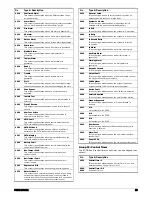
00: Global
The table below list the output function available in this group:
No
Type & Description
0000 Not
Used
This output type does not activate.
0001 AC
Fault
This output type activates when the mains supply has been
removed for the duration of the AC Fail timer.
0002 ATS
Fault
This output type activates when the onboard communicator
detects a phone line fault (Alarm Transmission Fault).
0003 Unset
This output type activates when the system is in the
disarmed state.
0004 Armed
This output type activates when the system is armed in any
of the armed modes (Away or Stay)
0005 Part
Armed
This output type activates when the system is armed in any
of the Stay armed modes.
0006 Armed/Alarm
This output type activates when the system is armed and
pulses when an alarm is generated.
0007 Bell
Active
This output type activates when an alarm is generated (it
may be delayed if the bell delay time is greater than zero).
The duration of this output type is controlled by the “Bell
Duration” timer.
0008 Strobe
Active
This output type activates when an alarm is generated and
deactivates when the system is reset
0009 Alarm
This output type activates when an intruder alarm is
generated.
Summary of Contents for EC-P8
Page 1: ...EC P8 8 18 Zone Intruder Alarm System Installation Manual...
Page 4: ...4 P0031 LI 02 01 1 System Overview System Configuration...
Page 45: ...P0031 LI 02 01 45 Notes...
Page 46: ...46 P0031 LI 02 01 Notes...
Page 47: ...P0031 LI 02 01 47 Notes...
Page 48: ...Technical Support Email support zetaalarmsystems com...


