Exothermics Tubular Heat Recuperators, Installation Guide 545, 3/20/2015
6
Receipt of Heat Recuperator
The heat recuperator should be inspected immediately for
any evidence of damage received in transit. If shipping
damage has occurred, a claim should be filed immediately
with the shipping company. Notify Exothermics, Inc. at
(419) 729-9726.
Installation
The heat recuperator may be installed indoors or outdoors
without the need for additional painting or protection.
Exothermics manufactures three different recuperator
designs: uninsulated, externally insulated, and internally
insulated; each design has it’s own installation
requirements.
Uninsulated Recuperator
All exterior surfaces have the potential to reach elevated
temperatures, therefore, personal protection must be
considered when installing this unit. Because all flange
connections are considered HOT connections, provisions
for expansion are required. Field insulation of the entire
system is recommended.
Externally Insulated Recuperator
These units are typically insulated with 4 to 6 inches
(102 to 152 mm) of insulation to all external surfaces
except the flange connections. The flange connections
and immediate surrounding surfaces, therefore, have the
potential to reach elevated temperatures. Personal
protection must be considered when installing this unit.
Because the flange connections are considered HOT
connections, provisions for expansion are required. Field
insulation of the flanges and surrounding surfaces should
be considered.
Internally Insulated Recuperator
These units are typically pre-insulated with 4 to 6 inches
(102 to 152 mm) of fiber modular insulation. The flange
connections are considered cold connections. Mating
connections must also be cold flanges. External insulation
is not recommended.
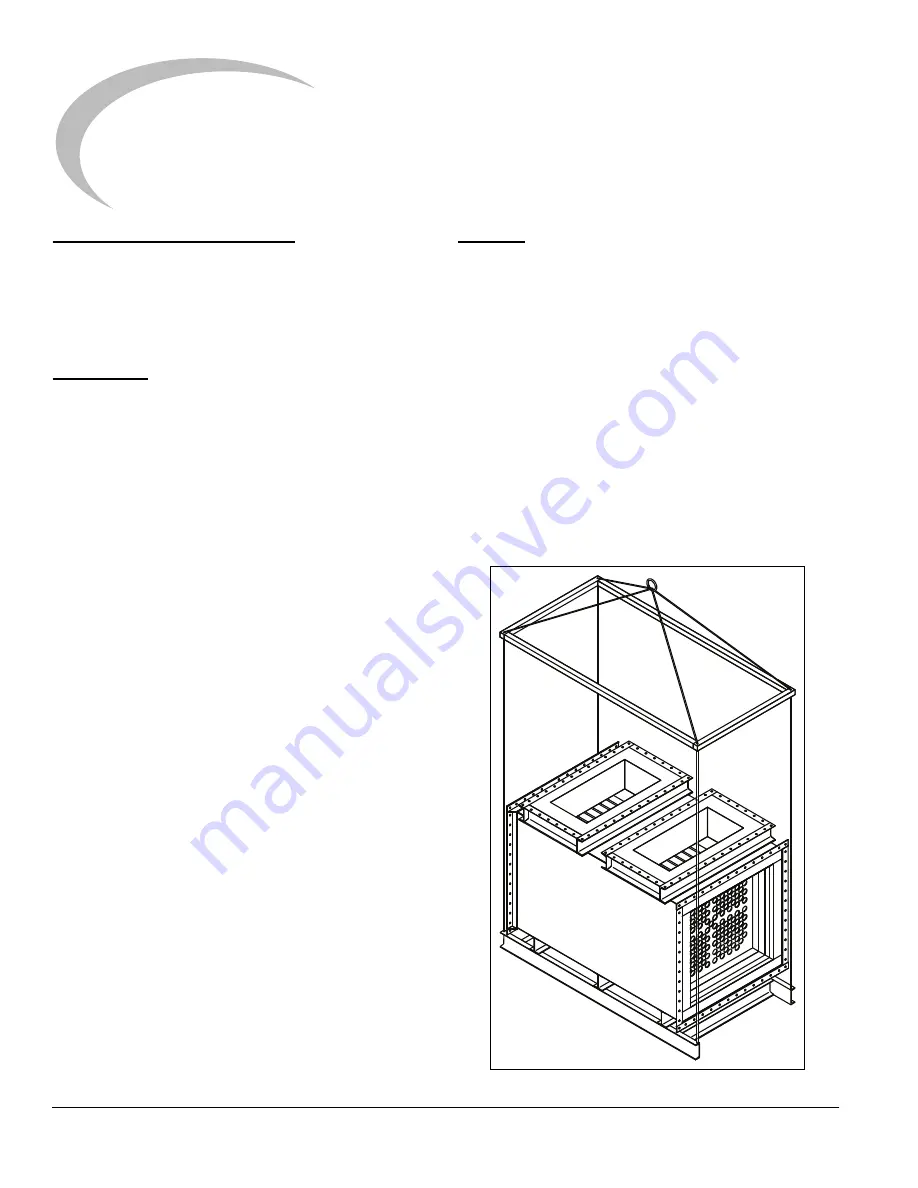
Rigging
When rigging the recuperator for handling by crane,
extreme care should be used to avoid damage to the
recuperator. The heat recuperator is NOT equipped with
lifting lugs. To minimize external loading on the heat
recuperator, a lifting frame should be fabricated from a
minimum of 8 inch (203 mm) channel, the same width and
length as the heat recuperator casing. Lifting slings may
then be attached to the lifting frame. Chains should be
avoided as they may cause external damage. The slings
may then be attached to the I beam supports on the
underside of the heat recuperator. The slings should be
vertical, so that no side loads are transmitted to the heat
recuperator casing or supports. Some units may have
external packaging, plywood covers, or external supports.
This packaging should not be removed until the unit is set
into place.
Figure 3.1.
Installation
3
Summary of Contents for Exothermics Tubular 545
Page 1: ...Exothermics Tubular Heat Recuperators 3 20 2015 Installation Guide 545...
Page 11: ...Notes ii...
Page 12: ......


