9
Eclipse ThermJet Self-Recuperative, V5, Installation Guide 208, 2/4/2013
■
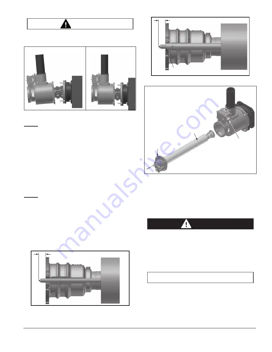
Do not allow the ceramic combustor to carry the
weight of the burner or the combustor will break.
Figure 3.6
NOTE:
The burner may require centering to assemble.
Nuts and bolts should be torqued to 15-20 ft-lbs (20-27
Nm) cold and re-torqued at operating temperature and
after 100 hours of operation. Position housing so air inlet
is oriented to align with the air manifold piping.
Step 5: Igniter
1. If already assembled, remove the rear cover
assembly by removing rear cover bolts. See Figure
3.9.
2. Thread igniter through rear cover and hole in nozzle.
See Figure 3.7 for burners without spark rod cooling
and Figure 3.8 for models with cooling.
NOTE:
Do
not
apply any grease to the threads of the
spark plug. You can cause bad grounding of the spark
plug if you apply grease to it. Bad grounding of the spark
plug results in a weak spark.
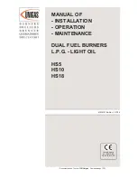
3. Slide the rear cover nozzle assembly through the air
inlet housing and into the combustor assembly. See
Figure 3.9.
4. Assemble the rear cover to the air inlet housing using
cap screws. Torque to 5 ft-lbs (7 Nm). Position cover
so gas inlet is aligned with gas manifold piping.
Figure 3.7
Figure 3.8
Figure 3.9
Step 6: UV Flame Sensing
1. Install the flame sensor into the designated opening in
the rear cover. See corresponding datasheet series
208 for proper location.
2. Make sure that the UV scanner is connected to the
electrical circuit of that burner.
■
Connecting the UV scanner of a burner to the
electrical circuit of a different burner can cause
fires and explosions.
The UV scanner must be compatible to the flame
monitoring control that is used. Refer to the manual of
your selected control for proper selection of the scanner.
■
Adjustments may vary from Eclipse published
values if the flame controls other than those
recommended in the Design Guide are used.
Consult with the engineer who specified the
alternate control for limitations.
CAUTION
CORRECT
WRONG
10 ± 2 mm
10 ± 2 mm
Spark rod cooling tube
should be flush with the nozzle
Rear Cover Nozzle
Assembly
Rear Cover
Bolts
Air
Inlet
Housing
DANGER
NOTICE


