background image

- 6 -

11

i

1

2

c

d

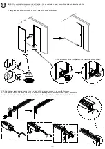
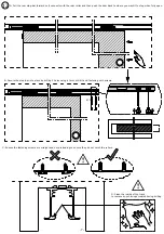
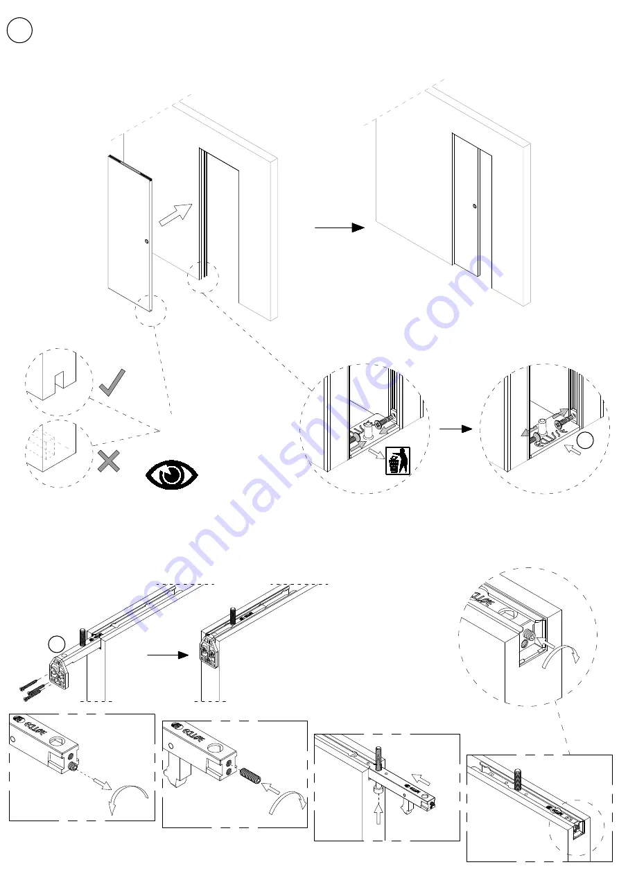
NOTE: If you intend to recess your door flush into the pocket when open, you will need to continue the rebate
in the base of the door right through to the front edge.

A: Hang the door back into the system in the reverse order of removal.

B: Insert the floor guide into place in the orientation shown below.

C: Slide the new rear hanging bracket into the back of the door and secure in place with 3 screws.
Slot the door back into the pocket half way and insert the leading hanging bracket. Once in place, remove the

black grub screw from the lower hole and screw it back in the upper hole to lock the bracket into the door.

Summary of Contents for Touch Latch AUTPP11

Page 1: ...ssembly and installation process your life will be easier A pair of tressles are very useful when assembling the frames Some parts may have sharp edges so use gloves and be careful when handling the p...

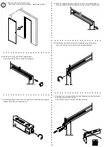
Page 2: ...B Remove the grey cap off the leading edge of the door at the top to reveal the brackets E Simultaneously slide and pivot the leading edge of the door out of the system to reveal the rear hanging bra...

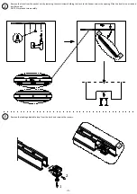
Page 3: ...ocket unit by removing the small screws holding the track to the header across the opening Slide the track to one side and it will drop out NOTE Store these screws safely Remove the leading adjustable...

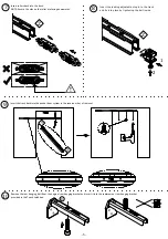
Page 4: ...bar and dispose of the adjustable stop Screw the Touch Latch to the stop bar with the screws provided as shown below Slide the Touch Latch and stop bar back into the track in the same orientation it...

Page 5: ...e leading adjustable stop in to the track and fix into place by tightening the bolt inside Insert the track back into the pocket door system in the reverse order of removal Remove the rear hanging bol...

Page 6: ...em in the reverse order of removal B Insert the floor guide into place in the orientation shown below C Slide the new rear hanging bracket into the back of the door and secure in place with 3 screws S...

Page 7: ...you want it to stop when fully open B Secure the stop bar into place by drilling 2 holes using a 3mm drill bit and fastening with screws C Ensure the fastening screws are straight and not protruding t...

Page 8: ...LISSE all rights reserved The use filing and total or partial reproduction using any mechanical or electronic means of texts drawings and pictures contained in this publication is strictly prohibited...

Reviews: