background image


E93.9950EN CB Cascade manual 

19


11.  Mounting the hydraulic group and the connecting sets 

After the boiler has been mounted on the frame, the hydraulic group and the connecting sets must be mounted. 
 

Attention! 

All lines/piping must be mounted free of tension. The weight of all the components should be supported 
separately from the boiler so there is no force on the connections. 
 

Attention! 

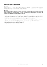
During mounting of the hydraulic and gas header group it is very important that the position of the support beam 
as well as the support brackets of the headers allow for some play (tolerance) for a neat installation. After 
finishing the installation, the support beam and brackets can be tightened. 


1.  Mount the support brackets for the return header at nominal height. See also Figure 7.2. 


2.  Place the return header(s) (bottom water header / blue) on the support brackets and fasten it (them) loosely 

with the U-bolts. Make sure that the connections for the corresponding connecting sets are at the back of 
the header.  


3.  Mount the connecting sets for the return header. See also Figure 7.3. 


Attention

An external pump (to be ordered separately) must be mounted between the return connecting set and the 
boiler. Required for this are: 

pump supplied with 2 flat-seal two-part couplings; 

1 flat-seal coupling for connection to boiler (inside thread / female thread) 

1 flat-seal coupling for connection to connecting set (outside thread / male thread) 

 
a.  Fit the flat-seal couplings to the boiler and to the connecting set. 
b.  Mount the pump to the boiler; pay attention to its orientation. 
c.  Mount the connecting set to the pump; pay attention to its orientation. 
d.  Bend the flexible part of the return connecting set into a smooth bend. 
e.  Fit the connecting set to the return header (conical three-part coupling). Fit the loose part to the header 

and then fasten the coupling. 
 

4.  Mount the support brackets for the supply header. See also Figure 7.2. 


5.  Place the supply header(s) (top water header / red) on the support brackets and fasten it (them) loosely with 

the U-bolts.  


6.  Mount the connecting sets for the supply header. See also Figure 7.3. 

The connecting set has a three-part coupling for the connection to the boiler. 


a.  Fit the loose part of the three-part coupling to the boiler. 
b.  Fit the connecting set to the coupling. 
c.  Fit the connecting set to the supply header (conical three-part coupling). Fit the loose part to the header 

and then fasten the coupling. 
 

7.  Fit the gas connecting sets to the boiler and to the gas header. 


8.  When all parts are mounted correctly and are free of tension, fasten all couplings, bolts and U-bolts. 


9.  Next mount the low loss header. See chapter 12. 


Summary of Contents for CB 85 CH

Page 1: ...Installation manual CASCADE SETUP Wall hung high efficiency central heating boilers CB 85 CH CB 105 CH CB 125 CH CB 155 CH INITIAL VERSION E93 9950EN S67 500 004 003 03...

Page 2: ......

Page 3: ...UNTING THE FRAME 15 8 1 Frame elements 15 8 2 Procedure for mounting the frame 16 9 MOUNTING THE GAS HEADER 17 10 MOUNTING THE BOILERS ON THE FRAME 18 11 MOUNTING THE HYDRAULIC GROUP AND THE CONNECTIN...

Page 4: ...ne boiler go into error the cascade configuration will continue to operate ECO Heating Systems can supply standard cascade systems with mounting frame piping and low loss headers for up to six boilers...

Page 5: ...d in detail in chapter 8 4 Mount the gas header This is described in detail in chapter 9 5 Mount the boilers on the frame This is described in detail in chapter 10 6 Mount the hydraulic group and the...

Page 6: ...9 2 2 CCB 249 2 0020 253 1 1 2 CCB 253 2 0101 255 3 3 CCB 255 3 3000 272 2 1 3 CCB 272 3 2100 276 1 1 2 CCB 276 2 0011 289 1 2 3 CCB 289 3 1200 295 2 1 3 CCB 295 3 2010 302 2 2 CCB 302 2 0002 305 3 3...

Page 7: ...050 650 4 1 5 CCB 650 5 0041 676 3 2 5 CCB 676 5 0032 702 2 3 5 CCB 702 5 0023 729 1 4 5 CCB 729 5 0014 748 6 6 CCB 748 6 0060 755 5 5 CCB 755 5 0005 775 5 1 6 CCB 775 6 0051 801 4 2 6 CCB 801 6 0042...

Page 8: ...guration In this chapter is explained how to determine the dimensions of the cascade configuration and how much space is required in the room where the cascade configuration will be installed Figure 4...

Page 9: ...AMPLES In case a cascade configuration for 275 kW is required which will exist of 2 boilers refer to Table 4 1 for the dimensions of the cascade configuration The table shows that frame length for thi...

Page 10: ...L3 length low loss header 487 487 H1 height gas 308 308 H2 height header coupling 257 257 H3 height couplings 380 380 D1 header connection size DN 80 PN6 3 DN 80 PN6 3 D2 header connection size DN 80...

Page 11: ...to the hydraulic and gas header groups Each connecting set contains one gas one supply and one return pipe More details can be found in chapter 6 5 Hydraulic and gas header group existing of 1 gas 1 s...

Page 12: ...lve ball valve coupling to return header Figure 6 1 Connecting sets The gas connecting set should be connected to the gas connection on the boiler The supply connecting set must be connected to the bo...

Page 13: ...2 Supply header red marking 3 Return header blue marking Figure 7 1 Parts hydraulic and gas header group 7 2 Support beam and support brackets Figure 7 2 Headers support beam and support brackets 1 2...

Page 14: ...Depending on the cascade configuration the headers come in the following size varieties Header Varieties Gas header DN50 DN80 Water header supply and return DN65 DN80 DN100 See also Table 4 1 Table 4...

Page 15: ...assembling the frame on which the boilers will be hung The basic frame exists of the following elements L shaped stands Top beam In between beam middle beam Mounting material bolts washers 1 Locking...

Page 16: ...e 8 1 To mount the frame subsequently carry out the steps in the following procedure 1 Check after unpacking that all parts are actually present 2 Mount the in between beam s between the L stands Ensu...

Page 17: ...eaders allow for some play tolerance for a neat installation After finishing the installation the support beam and brackets can be tightened 1 Mount the support beam s for the hydraulic and gas header...

Page 18: ...et with the locking strip to prevent the boiler from falling off the bracket see drawing 5 Make sure that the boiler is at the right position near level The boilers must hang backwards slightly 1 0 5...

Page 19: ...pplied with 2 flat seal two part couplings 1 flat seal coupling for connection to boiler inside thread female thread 1 flat seal coupling for connection to connecting set outside thread male thread a...

Page 20: ...installation 540 to 930 kW E68 0300 503 200 x 200 x 5 Table 12 1 Low loss header connection sizes The low loss header can be fitted on the right hand side as well as on the left hand side without maki...

Page 21: ...t be completed with all other necessary parts and connections This may include all valves non return valves strainers air separators expansion vessel overflow Attention The hydraulic piping of the Eco...

Page 22: ...the Installation Service Manual of the CB boiler series Flue gas and air supply system For each boiler the combined resistance of the individual flue gas and air inlet pipe can be calculated and check...

Page 23: ...ow to manage the parameters required for the cascade configuration is described in detail in the chapter s about Cascading in the Installation Service Manual of the CB boiler series Attention Changes...

Page 24: ...re 5 1 Cascade parts and groups 11 Figure 6 1 Connecting sets 12 Figure 7 1 Parts hydraulic and gas header group 13 Figure 7 2 Headers support beam and support brackets 13 Figure 7 3 Headers and conne...

Page 25: ...E93 9950EN CB Cascade manual 25 20 Appendix A Cascade Parts The following drawings give an overview of parts used in a cascade configuration Top view Front view 5 E67 5020 002...

Page 26: ...N65 DN80 DN100 11 Low loss header DN65 DN80 DN100 12 Gas connecting set 13 Gas connecting set 1 14 Supply connecting set R1 15 Return connecting set R1 16 Supply connecting set R1 Return connecting se...

Page 27: ......

Page 28: ...Your distributor Eco Heating Systems Groningen B V P O Box 5145 9700 GC Groningen Rigaweg 10 9723 TH Groningen The Netherlands T 31 0 50 5470470 E sales ecohs nl I www ecohs nl...

Reviews: