20
E93.9950EN CB Cascade manual
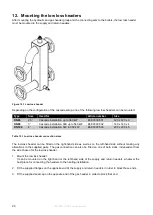
12. Mounting the low loss headers
After mounting the hydraulic and gas header group and the connecting sets to the boilers, the low loss header
must be mounted to the supply and return headers.
Figure 12.1 Low loss header
Depending on the configuration of the cascade setup, one of the following low loss headers can be mounted:
Type
Size
Used for
Article number
Size
DN 65
2,5”
Cascade installation up to 360 kW
E68.0300.501
120 x 120 x 3
DN 80
3”
Cascade installation 360 up to 540 kW
E68.0300.502
140 x 140 x 4
DN 100
4”
Cascade installation 540 to 930 kW
E68.0300.503
200 x 200 x 5
Table 12.1 Low loss header connection sizes
The low-loss header can be fitted on the right-hand side as well as on the left-hand side without making any
alterations to the supplied parts. The gas connection can also be fitted on one of both sides, independent from
the side chosen for the low loss header.
1. Mount the low loss header.
It can be mounted on the right-hand or the left-hand side of the supply and return headers, whatever the
best place for connecting the headers to the heating installation.
2. Fit the supplied flanges on the opposite end of the supply and return headers in order to block those ends.
3. Fit the supplied seal cap on the opposite end of the gas header in order to block that end.


