14
b) Mounting the FHT8V valve operating mechanism
Ö
Please note:
If no radiators are to be controlled in the room in which the control centre is installed, please skip the following
steps and continue with section c). Then switch off the control centre’s control function. Afterwards, the
control centre displays the current temperature measured in the room instead of the target temperature.
This is because the control centre should always be placed in the same room as the respective valve
operating mechanism, so that the room temperature can be controlled with the valve operating mechanism.
Otherwise, extreme temperature variations will result and the valve operating mechanism will be set
incorrectly. For example, the control centre measures 18°C in a living room and therefore turns the heating
up high. As the radiator is in another room, the control centre does notice the rising room temperature and
continues to turn up the radiator!
X
X
X
X
X
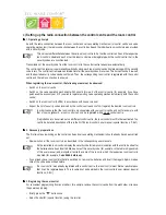
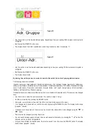
1. Removing the old thermostat
Remove the mechanical thermostat. If the screw connections have seized up you
can use multigrip pliers. Release the screw connection carefully by turning it
anticlockwise. See the arrow in figure 10.
Figure 10
X
X
X
X
X
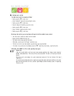
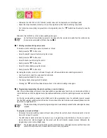
2. Inserting the batteries into the valve operating mechanism
• Remove the battery compartment cover of the valve operating mechanism by
sliding it down and out.
• Insert two AA batteries (preferably alkaline) in the battery compartment,
observing the correct polarity. You will find corresponding figures in the
battery compartment.
Operation using rechargeable batteries is possible, but may result in short
operation times or reduced ranges. If you experience these problems, use
alkaline batteries, as described.
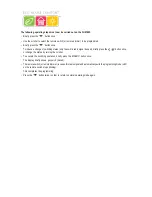
• ‘C1’ is displayed, followed by a two-digit number. ‘C2’ is then displayed,
followed by another two-digit number.
These two numbers are the two parts of the security code (e.g., ‘12’ and ‘34’
= security code ‘1234’).
• Afterwards a signal tone is emitted and ‘A1’ is displayed.
• The valve operating mechanism now fully retracts the control pin to facilitate
mounting.
• Afterwards ‘A2’ is displayed.
Figure 11
FHT 8W Heat Demand Relay
Installation and User Guide
Product Code EHC-FH06
1


