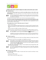
24
Ö
15 address groups are possible:
11, 12, 13, 14, 21, 22, 23, 24, 31, 32, 33, 34, 41, 42, 43
In order to be able to separately control each receiver, you need to program each receiver to a single address. In addition
to the address group that is already selected (room A: 11, room B: 12, room C: 13, room D: 14), a subaddress is also
needed.
Ö
The following 15 subaddresses are possible for each address group:
11, 12, 13, 14, 21, 22, 23, 24, 31, 32, 33, 34, 41, 42, 43
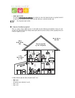
In the example the awning is programmed to the single address 1211, which comprises the address group 12 and its
subaddress 11.
All the receivers in room A have also been programmed to a local master address (1144 in the example).
Ö
For the local master address 44 is always set as the subaddress, while one of the 15 local master addresses
(11, 12, 13, 14, 21, 22, 23, 24, 31, 32, 33, 34, 41, 42, 43) can be selected via the address group.
Example:
1144, address group 11, subaddress 44
All the lamps in the house can be controlled via the global master address 4444.
The awning was deliberately not programmed to this address and can therefore only be addressed via its single address
(1211). It must be operated separately in this example.
The ceiling lamps in all the rooms are also combined in a function group (4411 in the example, address group 44,
subaddress 11) and can therefore be jointly controlled.
To select one of the 15 function groups, you need to set 44 as the address group and a value between 11 and 43 (11,
12, 13, 14, 21, 22, 23, 24, 31, 32, 33, 34, 41, 42, 43) as the subaddress.
X
X
X
X
X
6. Registering (adding) the remote switching components
Ö
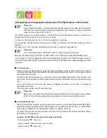
Before starting to register (add) the remote switching components with the control centre, you should
consider how you want to assign the addresses, as previously described.
Of course, this will be influenced by whether or not you are already operating transmitters and receivers from
the FS20 wireless control system. Changes may be required.
Only start to register the remote switching components with the FHZ1000 once you have carried out your
system planning.
For convenient programming from an armchair, for example, remove the control centre from the wall holder or remove
the power supply plug. When doing so, make sure that a 9V block battery is inserted in the FHZ1000 (the battery, of
course, must not be low...).
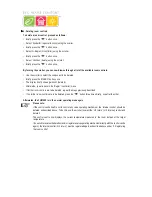
• Briefly press the ‘
x
’ button once.
• Select ‘Sonderfkt.’ (special function) using the scroller.
• Briefly press the ‘
x
’ button once.
• Select ‘Schalter’ (switch) using the scroller.
• Briefly press the ‘
x
’ button once.
• Select ‘Hinzufügen’ (add) using the scroller.
• Briefly press the ‘
x
’ button once.
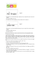
• The LCD shows ‘Adr.-Gruppe’ (address group) and a 2-digit random number, for example, ‘11’.
FHT 8W Heat Demand Relay
Installation and User Guide
Product Code EHC-FH06
1


