background image

15       

©2009 Eco-Orlan USA LLC.  All Rights 

Reserved


 Revised August 2009. 


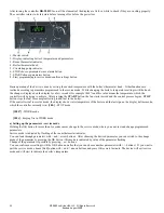
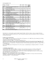
d) Boiler’s work temperature setting 

Minimal boiler temperature 

[L150]


Maximum boiler’s temperature 

[H195]


Boiler temperature hysteresis 

[h 10]

 - this parameter defines what value should the temperature of water in the boiler decrease by, 

below temperature set with the thermostat knob, to turn the pressure fan on. 


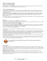
e) Boiler’s overheating protection 

Boiler overheating temperature 

[A210] 

– exceeding this value causes permanent turn off of the pressure fan and launch of the 

circulating pump, to prevent boiler overheating.  Overheating mode is indicated by boiler overheating indicator and by displaying 
error 

[E 2] 

on the display.  

It can be turned off by pressing the 

STOP

 button, but only when temperature decreases below boiler’s overheating temperature. 

Pressure fan turns off also in case of damage of the boiler’s temperature sensor, which is displayed on the display by error 

[E 1].


STB

 - the controller also has additional protection from overheating, which is independent from the processor.  In case of a 

temperature increase over 
200°F, the control process is turned off by turning the fan off and launching the circulating pump.  The fan and the pump are joined to 
the control process again, when temperature reaches 190°F. 


f) No fuel 

No-fuel testing time during fuel firing start 

[Fd60]

 - after switching to the 

WORK mode, if water temperature doesn't reach temperature set with the thermostat in programmed time, the control process will be 
turned off and the display will show the message: 

[FUEL].


You can return to the previous mode by pressing the 

STOP

 button. 

No-fuel testing time during work mode [

Fb30] 

- in 

WORK

 mode, if temperature of water in the boiler decreases below temperature 

set with the thermostat, by hysteresis value, and don't reach temperature set with the thermostat in programmed time, the control 
process will be turned off and the display will show the message: 

[FUEL].


You can cancel the alarm by pressing 

STOP

 button. 

 
Additional output work mode 

[Ar 0]

 - the controller has been equipped with a multipurpose output that can work in one of the 

following modes: 
*  mode

 [Ar 0]

 - output may control the oil or gas boiler if such boiler exists in the heating circuit.  After switching the controller on 

with the main power switch the additional boiler is turned off and it turns on again when there is no fuel in the solid fuel boiler.  This 
function is useful in heating systems where a solid fuel boiler is used to cut the heating costs. After erasing the no fuel alarm by 
pressing STOP button the additional boiler is again turned off and the controller works again 
* mode

 [Ar 1]

 - output may control the additional alarm signaling system.  Boiler temperature sensor malfunction, overheating and no 

fuel alarms will turn on the alarm 
*  mode 

[Ar 2]

 - output may control the mixing valve servo-motor.  Controlling the mixing valve requires a room thermostat to be 

present.  The mixing valve opens and closes depending on the room thermostat input.  Additionally, the mixing valve is opened in 
case of overheating or boiler’s temperature sensor malfunction. 


 In case of not having a room thermostat in the system, the room thermostat input contacts must be 


 short-circuited. 


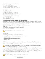
g) Device failures 

The controller is constantly testing if its internal circuits and temperature sensor are working correctly.  After detection of a fault, it 
stops the pressure fan, turns on the circulating pump and shows the proper error message on the display.  In case of failure please turn 
off the controller, plug the circulating pump to the power source, bypassing the controller, ensure appropriate fuel firing in the boiler 
and contact the service technician. 
When [

E 1]

 error appears on the display, it means fault (short-circuit) in the boiler sensor circuit or temperature below 32°F. 

[E 2]

 is displayed if boiler overheats. 

[E 3]

 error means fault and overheating at the same time.  Appearing of 

[E 1]

 error on the display without ability to cancel it by 

pressing STOP button, in spite of temperature below 190°F, may mean permanent damage of the boiler’s temperature sensor (e.g. if 
the boiler overheated above 300°F). 


Summary of Contents for Paxo Series

Page 1: ...1 2009 Eco Orlan USA LLC All Rights Reserved Revised August 2009 Operating Manual Paxo line of Orlan boilers Wood gasification boilers from 18 80 kW 75 275k Btu...

Page 2: ...c for the RK 2001UA Controller and the Module Connections 11 18 Temperature Controller 12 a Setting up the parameters service mode 13 b Pressure fan work parameters 14 c Circulating pump parameters 14...

Page 3: ...UV and CE Testing and certification for North American certifications UL 391 ETL and CSA are in progress Orlan boilers are efficient and environmentally friendly Heating your home and domestic water h...

Page 4: ...eral rule hardwood stacked for one year under cover is usually ready for use as a fuel in the Paxo boiler Wood that has been properly stored for two years is the best Wood is a fuel which can be stock...

Page 5: ...wood is burned in the top primary combustion chamber where heat from the flame breaks the wood structure down into charcoal and then into combustible gas This gas passes through the ceramic nozzle or...

Page 6: ...41 40 75 51 5 65 Hot water outlet I inch 13 4 12 6 12 6 24 0 24 0 Diameter of chimney flue J inch 8 0 8 0 8 0 8 0 8 0 Width with coil K inch 26 28 3 28 3 33 9 33 9 Height of coil connection L inch 39...

Page 7: ...or handle 10 Loading chamber gasification 11 Fan tap 12 Fan 13 Fan casing 14 Nozzle of refractory concrete 15 Secondary air adjustment 16 Combustion chamber 17 Bottom door 18 Smoke tube heat exchanger...

Page 8: ...te into these rooms a carbon monoxide alarm must be installed that can give a warning regarding possible escapes of carbon monoxide into the inhabited rooms As an additional precautionary measure the...

Page 9: ...That can be easily checked by opening a window or door to see if the problem goes away 13 Boiler Set Up The boiler is shipped completely assembled and ready for installation and use The boiler should...

Page 10: ...stem needs to be changed e g due to outside temperature changes seasonal changes A four way mixing valve is an essential component of any Paxo boiler installation Four way mixing valves can be used in...

Page 11: ...which will corrode the boiler and other parts over time if enough oxygen is allowed into the system For freeze protection use only non toxic hydronic heating system antifreeze available from plumbing...

Page 12: ...multipurpose output which allows connecting the mixing valve the alarm signal or an additional gas or oil boiler Before turning on the device by master switch connect controller pressure fan and circu...

Page 13: ...START button the fan starts to work and the control process begins STOP button stops the fan for example allowing to add fuel to the boiler If the controller isn t in service mode the display shows wa...

Page 14: ...which you can return by choosing the Prod option b Pressure fan work parameters Fan power 100 this value defines power of the fan When r parameter is set to 0 10 this is the maximum power of the fan...

Page 15: ...m by pressing STOP button Additional output work mode Ar 0 the controller has been equipped with a multipurpose output that can work in one of the following modes mode Ar 0 output may control the oil...

Page 16: ...this state 7 Add more wood 8 Wait another 15 to 20 minutes for a charcoal layer to accumulate 9 Close both upper and lower doors 10 Pull the bypass damper closed toward you and switch on the controlle...

Page 17: ...below 140 F This can be achieved with a properly installed 3 way or 4 way mixing valve 22 Primary Secondary and Blower Air Inlet Settings A critical phase of successful set up of a Paxo boiler for op...

Page 18: ...e primary air inlets determine how much air is available in the primary upper combustion chamber where the fuel undergoes pyrolysis The secondary air inlets regulate how much air goes into the steel t...

Page 19: ...e new shape of the sealing rope To do that remove the door loosen the cap turn the hinge 360 and tighten the blocking nut to block the hinge retaining screw The upper and lower hinges should be adjust...

Page 20: ...oo moist Use properly seasoned wood Primary or secondary air conduit choked Call service not covered by warranty Wrong regulation of the air and wood gas Call service not covered by warranty Nozzle da...

Reviews: