background image

 
The Burner Reset button on the Control Box illuminates to indicate that a lockout has occurred. 
 
In the event of the Burner locking out, do not attempt to restart the Burner by pressing the Reset Button on 
the Burner Control Box for at least 2 minutes. A Bi-metallic timer within the Control Box has a minimum 
cooling time of 45 seconds thus the 2 minute interval will ensure that this Bi-metallic timer has cooled and is 
therefore in a position where it may be reset. 


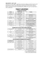
RESTARTING AFTER LOCKOUT 

When lockout has occurred, inspect for any obvious causes e.g. oil leaks. Also check the fuel line from the 
tank to the boiler and that any oil shut off valve has not been inadvertently closed.   


RESTART 

-


Check there is adequate oil in the storage tank. 

-


Check oil supply valves are open 

-


Switch on heating system (e.g. Time Clock) 

-


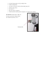
Press the Burner Reset Button on the burner Control Box, which will be illuminated. The Burner Reset 
Button (illuminated)(Fig 1) will go out and the burner will commence the ignition start sequence. After 
15 seconds the Burner should fire normally. 


PLEASE NOTE:

 Should the Burner not start, the lockout indicator, on the Control Box/Burner Reset 

Button will illuminate again. 
- Wait at least 3 minutes and press the Burner Reset Button again. 
Failure to start a second time indicates a fault requiring attention. 
 
In the event of a second failure to start: 

-


Switch off electrical supply 

-


Call service engineer.  


REGULATIONS 

The installation of oil-fired boilers should comply with the following standards and codes of practice: 
 
- BS5449 


Forced circulation hot water heating systems for domestic use. 

- BS5410-Part 1 Oil installations up to 45kw 

- BS7593 


Water treatment of hot water central heating systems 

- BS7671 


Electrical Regulations 

- Building Regulations Part 1L and J 2002 England and Wales, Part F Scottish Regulations and 

Technical Booklet L Northern Ireland. 

- OFTEC 


Codes of Practice Published or Recommended. 

 
After installing, the system needs to be flushed with a cleanser like Fernox Heavy Duty Restore, for fast-
acting removal of lime scale, black sludge (magnetite) and other deposits from the boiler and the central 
heating system. Then add a Fernox protector to give long-term protection of the central heating system 
against internal corrosion lime scale formation. 


Summary of Contents for 15/21

Page 1: ...Eire GB IE Instructions for Use Installation and Servicing This appliance must be installed in accordance with the regulations in force and only used in an adequately ventilated space Please read thes...

Page 2: ...ime is taken to read these instructions carefully before installation and use of the appliance In order for the warranty to remain valid it is imperative that the appliance be installed in compliance...

Page 3: ...ended when applicable Children should be supervised at all times if in the vicinity of the cooker In the interest of hygiene and safety the cooker should be kept clean at all times The cooker is desig...

Page 4: ...when works are complete Always ensure appliance is electrically dead prior to working on the electrics 3 Technical Specification Appliance type Cooker and Space heater Cooker Burner System Eco Flame...

Page 5: ...ble for deep fat frying shallow frying and boiling The surfaces of the hotplates are ground flat and it is therefore recommended that all utensils used have a solid flat base to come in complete conta...

Page 6: ...r remains fully functional and in a safe condition 5 0 Delivery and Transport Your Eco Range Cooker is an extremely heavy and solid appliance When attempting to move or transport your cooker please ta...

Page 7: ...d flue allows the cooker to be placed against an outside wall with either rear or top outlet concentric flue Maximum length of rear flue 500mm Maximum length of top outlet flue 300mm vertical 500mm ho...

Page 8: ...f 3 drop 6 With suitable material make a good flue hole 7 Fit the terminal to the pipes whilst ensuring the inner pipe has adequate clearance between terminal end and outlet min 50 mm Secure terminal...

Page 9: ...t go up the chimney have quite a high temperature 200 C 260 C and are made up of a few different types of gases A condensing boiler is designed so that these flue gases pass through a stainless steel...

Page 10: ...n the boiler is controlled and maintained by the Boiler Control Thermostat located on the boiler control panel TEMPERATURE SETTINGS The Boiler Control Thermostat has a range of 50 C to 80 C The recomm...

Page 11: ...URNER LOCKOUT The burner has an independent control system Burner Control Box this includes a flame detector Photocell which senses the presence of a flame In the event of a flame failure the burner c...

Page 12: ...rner should fire normally PLEASE NOTE Should the Burner not start the lockout indicator on the Control Box Burner Reset Button will illuminate again Wait at least 3 minutes and press the Burner Reset...

Page 13: ...waste drainage system Soil vent stack External Drainage system External condensate absorption point NOTE condensate pipe work must fall at least 50mm per metre towards the outlet ensuring all joints a...

Page 14: ...RECOMMENDED FLUE POSITION...

Page 15: ...OIL SUPPLY...

Page 16: ...oiler must be wired using a double pole isolating switch 230v 50hz fused 5 amps The mains supply must be connected with the boiler dual stat the supply will then continue down to the burner control bo...

Page 17: ...out debris Clean baffle assembly Pull out inserts from stainless steel heat exchanger and clean before replacing Ensure stainless steel heat exchanger is thoroughly cleaned Empty and clean condensing...

Page 18: ...BOILER SIZE NO OF INSERTS FROM L H SIDE OF CONDENSER REMAINING TUBES WITHOUT INSERTS 15 21 KW 10 6 1 SET OF BAFFLES 15 21 KW...

Page 19: ...front A service access space of at least 700mm should be made available at the front of the boiler THE HEARTH The temperature of the surface below the boiler is less than 85 C If the floor under the...

Page 20: ...to the boiler De pressurise heating system and check expansion vessel pre charge is the same as the cold fill pressure of the heating system Expansion vessel pre charge must not exceed 1 5 bar Remove...

Page 21: ...al operating temperature Check the smoke reading Measure the Co2 Measure net flue gas temperature Check domestic hot water flow and hot temperature is acceptable to the householder PLEASE NOTE Reducin...

Page 22: ...n and time clock is calling for heat Mains indicator green should be illuminated If green light is not illuminated and fuse has been checked then heating system charge may be low check black needle on...

Page 23: ...er using recognised test equipment and that the relevant section of the latest edition of BS 5410 Part 1 is read and fully adhered to The following warranty registration page should be completed by th...

Page 24: ...NICIANS DETAILS Technician s Name in BLOCK CAPITALS Technician s Competent Persons OFTEC Registration Number Address Town County Postcode Technician s Signature Cooker Boiler Burner pressure psi CO2 C...

Page 25: ...S Engineer s Name in BLOCK CAPITALS Engineers Registration Number Engineer s Signature Date COMBUSTION ANALYSIS Cooker Boiler Pump pressure CO2 CO ppm Flue Gas Temperature CO CO2 Efficiency Engineer s...

Page 26: ...S Engineer s Name in BLOCK CAPITALS Engineers Registration Number Engineer s Signature Date COMBUSTION ANALYSIS Cooker Boiler Pump pressure CO2 CO ppm Flue Gas Temperature CO CO2 Efficiency Engineer s...

Page 27: ...S Engineer s Name in BLOCK CAPITALS Engineers Registration Number Engineer s Signature Date COMBUSTION ANALYSIS Cooker Boiler Pump pressure CO2 CO ppm Flue Gas Temperature CO CO2 Efficiency Engineer s...

Page 28: ...S Engineer s Name in BLOCK CAPITALS Engineers Registration Number Engineer s Signature Date COMBUSTION ANALYSIS Cooker Boiler Pump pressure CO2 CO ppm Flue Gas Temperature CO CO2 Efficiency Engineer s...

Page 29: ...S Engineer s Name in BLOCK CAPITALS Engineers Registration Number Engineer s Signature Date COMBUSTION ANALYSIS Cooker Boiler Pump pressure CO2 CO ppm Flue Gas Temperature CO CO2 Efficiency Engineer s...

Page 30: ...S Engineer s Name in BLOCK CAPITALS Engineers Registration Number Engineer s Signature Date COMBUSTION ANALYSIS Cooker Boiler Pump pressure CO2 CO ppm Flue Gas Temperature CO CO2 Efficiency Engineer s...

Page 31: ...S Engineer s Name in BLOCK CAPITALS Engineers Registration Number Engineer s Signature Date COMBUSTION ANALYSIS Cooker Boiler Pump pressure CO2 CO ppm Flue Gas Temperature CO CO2 Efficiency Engineer s...

Page 32: ...S Engineer s Name in BLOCK CAPITALS Engineers Registration Number Engineer s Signature Date COMBUSTION ANALYSIS Cooker Boiler Pump pressure CO2 CO ppm Flue Gas Temperature CO CO2 Efficiency Engineer s...

Page 33: ...S Engineer s Name in BLOCK CAPITALS Engineers Registration Number Engineer s Signature Date COMBUSTION ANALYSIS Cooker Boiler Pump pressure CO2 CO ppm Flue Gas Temperature CO CO2 Efficiency Engineer s...

Page 34: ...it is consequently acknowledged that errors and omissions may occur This publication is intended only to assist the reader in the use of our products Eco Range Cookers will not accept any liability fo...

Page 35: ...Eco Range Cookers 60 Wincheap Canterbury Kent CT1 3RS info ecorangecooker co uk www ecorangecooker co uk...

Reviews: