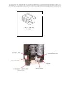
background image

Ovens -  


Height  


270mm 


Depth  


500mm 


Width  


345mm 


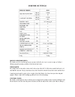
Your cooker is fitted with a thermostatic control device. This operating system provides the 
exact  heat  requirements  selected  (by  the  user)  for  cooking  and  reduces  the  overall  oil 
consumption.  The  user  selects  the  desired  cooking  temperature  and  when  the  cooker 
approaches the  selected operating temperature the thermostatic control operates to turn off 
the burner flame to maintain a steady temperature. The control knob on the device is marked 
which relates to a particular temperature setting of the top oven. 


4.1 Using your hotplates


Your  appliance  has  two  hotplates,  with  a  joint  hotplate  in  the  middle,  protected  with  two 
insulated lids which should remain in a closed position when not using the hotplate. The lids 
can  be  raised  independently  if  only  using  one  hot  plate.  The  hot  plate  temperature  is 
dependent on the setting of oven temperature. The higher the temperature in the ovens, the 
hotter the hotplate will become. 
The design of the hot plates is such that the left hand side will become the hottest, making 
this suitable for deep fat frying, shallow frying and boiling.  


The  surfaces  of  the  hotplates  are  ground  flat  and  it  is  therefore  recommended  that  all 
utensils  used  have  a  solid,  flat  base  to  come  in  complete  contact  with  the  hot  plate  for 
efficient results.  

4.2 Using your Ovens 


Your  appliance  has  2  ovens.  The  thermostatic  dial  in  the  top  oven  door  provides  an 
indication  to  the  top  oven  temperatures.  This  thermometer  reading  will  reduce  quite 
dramatically when the door is opened and only recover slowly when the door is closed. This 
occurrence  does  not  mean  that  the  oven  temperature  has  reduced.  The  bottom  oven  is 
warmed  by  the  underside  of  the  oven  above.  Depending  on  the  control  device  setting  and 
operational  time,  this  oven  will  generally  operate  some  85  –  90°C  below  the  top  ovens.  It 
may  be  used  for  small  food  cooking,  biscuits,  cakes  etc  but  it  is  best  used  as  a  warming 
compartment. 


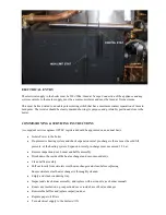
4.3 Overheat thermostat 

 
The  cooker  is  protected  by  an  overheat  thermostat  designed  to  shut  down  the  burner  if  a 
fault  occurs  leading  to  excessive  oven  temperatures.  The  overheat  thermostat  is  located 
below  the  control  device,  inside  the  lower  left  compartment.  To  reset,  unscrew  the 
protective cap and press the button. 


NOTE: If overheat reset occurs more than once contact your service technician. 


Summary of Contents for 15/21

Page 1: ...Eire GB IE Instructions for Use Installation and Servicing This appliance must be installed in accordance with the regulations in force and only used in an adequately ventilated space Please read thes...

Page 2: ...ime is taken to read these instructions carefully before installation and use of the appliance In order for the warranty to remain valid it is imperative that the appliance be installed in compliance...

Page 3: ...ended when applicable Children should be supervised at all times if in the vicinity of the cooker In the interest of hygiene and safety the cooker should be kept clean at all times The cooker is desig...

Page 4: ...when works are complete Always ensure appliance is electrically dead prior to working on the electrics 3 Technical Specification Appliance type Cooker and Space heater Cooker Burner System Eco Flame...

Page 5: ...ble for deep fat frying shallow frying and boiling The surfaces of the hotplates are ground flat and it is therefore recommended that all utensils used have a solid flat base to come in complete conta...

Page 6: ...r remains fully functional and in a safe condition 5 0 Delivery and Transport Your Eco Range Cooker is an extremely heavy and solid appliance When attempting to move or transport your cooker please ta...

Page 7: ...d flue allows the cooker to be placed against an outside wall with either rear or top outlet concentric flue Maximum length of rear flue 500mm Maximum length of top outlet flue 300mm vertical 500mm ho...

Page 8: ...f 3 drop 6 With suitable material make a good flue hole 7 Fit the terminal to the pipes whilst ensuring the inner pipe has adequate clearance between terminal end and outlet min 50 mm Secure terminal...

Page 9: ...t go up the chimney have quite a high temperature 200 C 260 C and are made up of a few different types of gases A condensing boiler is designed so that these flue gases pass through a stainless steel...

Page 10: ...n the boiler is controlled and maintained by the Boiler Control Thermostat located on the boiler control panel TEMPERATURE SETTINGS The Boiler Control Thermostat has a range of 50 C to 80 C The recomm...

Page 11: ...URNER LOCKOUT The burner has an independent control system Burner Control Box this includes a flame detector Photocell which senses the presence of a flame In the event of a flame failure the burner c...

Page 12: ...rner should fire normally PLEASE NOTE Should the Burner not start the lockout indicator on the Control Box Burner Reset Button will illuminate again Wait at least 3 minutes and press the Burner Reset...

Page 13: ...waste drainage system Soil vent stack External Drainage system External condensate absorption point NOTE condensate pipe work must fall at least 50mm per metre towards the outlet ensuring all joints a...

Page 14: ...RECOMMENDED FLUE POSITION...

Page 15: ...OIL SUPPLY...

Page 16: ...oiler must be wired using a double pole isolating switch 230v 50hz fused 5 amps The mains supply must be connected with the boiler dual stat the supply will then continue down to the burner control bo...

Page 17: ...out debris Clean baffle assembly Pull out inserts from stainless steel heat exchanger and clean before replacing Ensure stainless steel heat exchanger is thoroughly cleaned Empty and clean condensing...

Page 18: ...BOILER SIZE NO OF INSERTS FROM L H SIDE OF CONDENSER REMAINING TUBES WITHOUT INSERTS 15 21 KW 10 6 1 SET OF BAFFLES 15 21 KW...

Page 19: ...front A service access space of at least 700mm should be made available at the front of the boiler THE HEARTH The temperature of the surface below the boiler is less than 85 C If the floor under the...

Page 20: ...to the boiler De pressurise heating system and check expansion vessel pre charge is the same as the cold fill pressure of the heating system Expansion vessel pre charge must not exceed 1 5 bar Remove...

Page 21: ...al operating temperature Check the smoke reading Measure the Co2 Measure net flue gas temperature Check domestic hot water flow and hot temperature is acceptable to the householder PLEASE NOTE Reducin...

Page 22: ...n and time clock is calling for heat Mains indicator green should be illuminated If green light is not illuminated and fuse has been checked then heating system charge may be low check black needle on...

Page 23: ...er using recognised test equipment and that the relevant section of the latest edition of BS 5410 Part 1 is read and fully adhered to The following warranty registration page should be completed by th...

Page 24: ...NICIANS DETAILS Technician s Name in BLOCK CAPITALS Technician s Competent Persons OFTEC Registration Number Address Town County Postcode Technician s Signature Cooker Boiler Burner pressure psi CO2 C...

Page 25: ...S Engineer s Name in BLOCK CAPITALS Engineers Registration Number Engineer s Signature Date COMBUSTION ANALYSIS Cooker Boiler Pump pressure CO2 CO ppm Flue Gas Temperature CO CO2 Efficiency Engineer s...

Page 26: ...S Engineer s Name in BLOCK CAPITALS Engineers Registration Number Engineer s Signature Date COMBUSTION ANALYSIS Cooker Boiler Pump pressure CO2 CO ppm Flue Gas Temperature CO CO2 Efficiency Engineer s...

Page 27: ...S Engineer s Name in BLOCK CAPITALS Engineers Registration Number Engineer s Signature Date COMBUSTION ANALYSIS Cooker Boiler Pump pressure CO2 CO ppm Flue Gas Temperature CO CO2 Efficiency Engineer s...

Page 28: ...S Engineer s Name in BLOCK CAPITALS Engineers Registration Number Engineer s Signature Date COMBUSTION ANALYSIS Cooker Boiler Pump pressure CO2 CO ppm Flue Gas Temperature CO CO2 Efficiency Engineer s...

Page 29: ...S Engineer s Name in BLOCK CAPITALS Engineers Registration Number Engineer s Signature Date COMBUSTION ANALYSIS Cooker Boiler Pump pressure CO2 CO ppm Flue Gas Temperature CO CO2 Efficiency Engineer s...

Page 30: ...S Engineer s Name in BLOCK CAPITALS Engineers Registration Number Engineer s Signature Date COMBUSTION ANALYSIS Cooker Boiler Pump pressure CO2 CO ppm Flue Gas Temperature CO CO2 Efficiency Engineer s...

Page 31: ...S Engineer s Name in BLOCK CAPITALS Engineers Registration Number Engineer s Signature Date COMBUSTION ANALYSIS Cooker Boiler Pump pressure CO2 CO ppm Flue Gas Temperature CO CO2 Efficiency Engineer s...

Page 32: ...S Engineer s Name in BLOCK CAPITALS Engineers Registration Number Engineer s Signature Date COMBUSTION ANALYSIS Cooker Boiler Pump pressure CO2 CO ppm Flue Gas Temperature CO CO2 Efficiency Engineer s...

Page 33: ...S Engineer s Name in BLOCK CAPITALS Engineers Registration Number Engineer s Signature Date COMBUSTION ANALYSIS Cooker Boiler Pump pressure CO2 CO ppm Flue Gas Temperature CO CO2 Efficiency Engineer s...

Page 34: ...it is consequently acknowledged that errors and omissions may occur This publication is intended only to assist the reader in the use of our products Eco Range Cookers will not accept any liability fo...

Page 35: ...Eco Range Cookers 60 Wincheap Canterbury Kent CT1 3RS info ecorangecooker co uk www ecorangecooker co uk...

Reviews: