background image

11/18

70°

130°

23

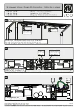
Die Feststellanlage ist für einen Türöffnungswinkel von 90° vormontiert. Der Öffnungswinkel lässt sich durch Verschieben der Feststelleinheit 
in Richtung Türmitte bis auf 70° und Richtung Türbänder bis auf 130° verstellen. Hierzu wird die Tür auf den gewünschten Feststellwinkel 
geöffnet und festgesetzt. Zum Verschieben der Feststelleinheit muss die Klemmschraube gelöst werden. Die Feststelleinheit dann auf 
Anschlag an das Gleitstück schieben und Klemmschraube anziehen. Beim max. Türöffnungswinkel kleiner 90° kann das Gleitstück die 
Klemmschraube verdecken. In diesem Falle muss die Feststelleinheit vor dem Öffnen und Festsetzen der Tür auf Anschlag in Richtung 
Türmitte nach Lösen der Klemmschraube verschoben werden. Klemmschraube wieder festziehen und wie vorher beschrieben den 
gewünschten Feststellwinkel einstellen.

Funktionsprüfung der Feststellung durchführen!

The slide rail with hold-open function is premounted for a door opening angle of 90°. The open angle can be changed up to 70° by moving the 
hold open unit in the direction of the door middle. It can also be changed up to 130° by moving the hold open unit in the direction of the door 
hinges. This is achieved by opening the door until the requested opening angle is achieved and fixing it in this position. In order to move the 
hold open unit, you have to loosen the fixing screw. Move the hold-open unit till dead stop of the sliding block and tighten the fixing screw. In 
case the max. door opening angle is smaller than 90°, the sliding block might cover the fixing screw. In this case, the hold-open unit has to be 
moved till dead stop in direction of door middle after fixing screw has been loosened. This has to be done before the door is opened and fixed 
in wished position. Tighten fixing screw and adjust (as described above) the requested hold-open angle.

Carry out a functionality test of hold-open function.

Le sélecteur de fermeture est pré-disposé pour un angle d’ouverture de 90°. Cet angle peut être modifié en dévissant les vis pointeaux et en 
déplacant l’arrêt de 70 à 130°. De cette façon la porte peut être maintenue à l’angle d’ouverture souhaité.

Tester le fonctionnement.

SW 2,5

22

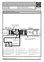
Funktionsprüfung des Rauchmelders
Functional check of smoke detector
Test fonctionnel de détecteur de fumée

Montageanleitung / Assembly instruction / Notice de montage

FSA 

ECO

 SR-EFR  

FSA 

ECO

 SR-EFR

FSA 

ECO

 SR-EFR

(DIN links / DIN rechts spiegelbildlich)
(DIN left / DIN right mirror image)
(DIN gauche / DIN droite inverser l‘illustration)

Summary of Contents for FSA ECO SR-EFR

Page 1: ...r for mounting as well as adjusting the valves of the doorcloser Pour le montage et le r glage des ferme portes merci d utiliser la notice de pose incluse s par ment Leistungserkl rung nach Verordnung...

Page 2: ...r raccordement lectrique 230V 120 Montage mit Adaptionsprofil 30mm Lochgruppe 120 428 5mm Mounting with adaptor plate 30mm hole group 120 428 5mm Montage avec profil d adaptation 30mm per age 120 428...

Page 3: ...428 5mm Montage avec profil standard 20mm per age 120 428 5mm Montage mit Adaptionsprofil 30mm Lochgruppe 120 428 5mm Mounting with adaptor plate 30mm hole group 120 428 5mm Montage avec profil d adap...

Page 4: ...28 5mm Montage avec profil standard 20mm per age 120 428 5mm Montage mit Adaptionsprofil 30mm Lochgruppe 120 428 5mm Mounting with adaptor plate 30mm hole group 120 428 5mm Montage avec profil d adapt...

Page 5: ...Nichtbeachtung entf llt jeglicher Garantieanspruch Diese Anleitung ist vom Monteur nach der Montage an den Betreiber weiterzugeben The electrical installation has to be made by a qualified person acco...

Page 6: ...M3x4 F r die Montage des T rschlie ers beachten Sie bitte die dem T rschlie er beiliegende separate Montageanleitung Refer to the enclosed assemby instruction of the doorcloser for mounting of the do...

Page 7: ...incluse s par ment nicht bei allen T rschlie ertypen verf gbar not available on all types of door closers Pas disponible sur tous les types de ferme portes Einstellungen T rschlie er Adjustments of th...

Page 8: ...2 90 3 SW2 5 SW2 5 Montageanleitung Assembly instruction Notice de montage FSA ECO SR EFR FSA ECO SR EFR FSA ECO SR EFR DIN links DIN rechts spiegelbildlich DIN left DIN right mirror image DIN gauche...

Page 9: ...eaf S reaches a closing angle of approx 30 Test du s lecteur SR Ouvrir les deux vantaux 60 le vantail principal G doit se maintenir en position ouverte Le vantail secondaire S doit se fermer Le vantai...

Page 10: ...1 M3x6 Montageanleitung Assembly instruction Notice de montage FSA ECO SR EFR FSA ECO SR EFR FSA ECO SR EFR DIN links DIN rechts spiegelbildlich DIN left DIN right mirror image DIN gauche DIN droite i...

Page 11: ...irection of the door hinges This is achieved by opening the door until the requested opening angle is achieved and fixing it in this position In order to move the hold open unit you have to loosen the...

Page 12: ...ue Bleu Braun Brown Brun Anschluss des Schutzleiters Connecting the protective earth conductor Connexion du conducteur de protection 26 25 Gr n zu 6 Green to 6 Vert 6 Braun zu Minus Brown to minus Bru...

Page 13: ...f 5 WICHTIG Bridge 1 to 5 IMPORTANT Pont 1 sur 5 IMPORTANT K 1 B Rauchschaltzentrale Auslieferungszustand Smoke switch control unit factory setting Centrale d tection de fum e montage d usine Montagea...

Page 14: ...e d usine D connecter le c ble du bornier 1 de NAG 02 et connecter au bornier K du NAG 02 Etape 2 Connexion de bouton poussoir externe Connecter le bouton poussoir externe aux borniers K et 1 de NAG 0...

Page 15: ...cke schwarz vom ORS 142 W vom Steckplatz 1 zu Schritt 2 Anklemmen der externen Deckenmelder 1 rot vom ORS TDS auf 1 ORS 142 W 2 blau vom ORS TDS auf 2 ORS 142 W 4 braun vom ORS TDS auf 5 ORS 142 W Ste...

Page 16: ...TDS sur K de NAG 02 Etape 3 Connexion de bouton poussoir externe Connecter le bouton poussoir externe aux borniers 5 de ORS 142 W et K de NAG 02 Step 1 Re wiring of the delivery status Remove bridge b...

Page 17: ...aus dem Umfeld der Anlage S ubern und entfetten der Gleitschiene speziell Laufwege der Gleitschuhe Bremsbereich S ubern und entfetten aller beweglichen Bauteile au er Gleitschuhe in den Gleitschienen...

Page 18: ...lastung erachtet der Hersteller zumindest eine j hrliche Wartung als notwendig H u gere Belastung erfordert kleinere Intervalle Montageanleitung Assembly instruction Notice de montage FSA ECO SR EFR F...

Reviews: