Chapter I Page 7
I.5. First start-up.
•
Check all connections have been properly made and the voltage at the terminals is
the right one.
•
Check that the seacock valve (1) is open and the 3 way valve (11) is in
“PRUEBA/TEST”
position, as in the diagram, so that the first water produced can be
rejected (17).
•
Switch on the system and check that the rotation direction is correct.
•
Check that pressure in the control panel pressure gauge (5) lies between
approximately 10 and 12 kg/cm
2
, and does not exceed 15 kg/cm
2
under any
circumstances (red zone).
•
High pressure will gradually rise before stabilising at approximately 50-60 kg/cm
2
.
There may be some differences in the pressure due to possible changes in the water
temperature.
•
During the first few minutes, the control panel flow meter (12) will display irregular
flow and air bubbles. These bubbles come from the interior of the membrane and
other components of the system, causing some irregularity in the high pressure
hydraulic pump cycles. They normally disappear without it being necessary purging
the circuit.
•
Approximately 10 minutes after the start-up, the “control tank” (17) should contain
about 10 liter water produced (1 liter/minute), what determines that the production
rate is correct. Stop the feed pump and put the 3 way valve (2) in FLUSH position,
then switch on the feed pump for about 2 minutes. By that time, a significant
reduction in both high and low pressure will be noticed, due to the fact that the fresh
water will have reached the membranes. This operation should be repeated twice at
least, to clean the new membranes and eliminate the membrane preservative that
may have accumulated inside. During the flushing, the pressurized fresh water
system in the boat must be “ON”, providing approximately 5 liters per minute flow,
at 2 Pressure Bars.
Summary of Contents for WATER-PRO MODULAR B-60
Page 4: ...CHAPTER I INTALLATION OPERATION AND MAINTENANCE ...
Page 14: ...CHAPTER II STORAGE AND CLEANING ...
Page 19: ...CHAPTER III PARTS LISTING EXPLODED VIEW OF THE ST 15 CERAMIC ECO SISTEMS PUMP ...
Page 23: ...CHAPTER IV FILTERS AND MEMBRANE REPLACEMENT ...
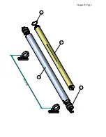
Page 26: ... F L O W E N T R A D A S A L I D A 1 2 3 7 M A X 9 3 5 m m Chapter IV Page 3 ...


