


866.463.2611 • www.ecosystemsdisplays.com
Step 1
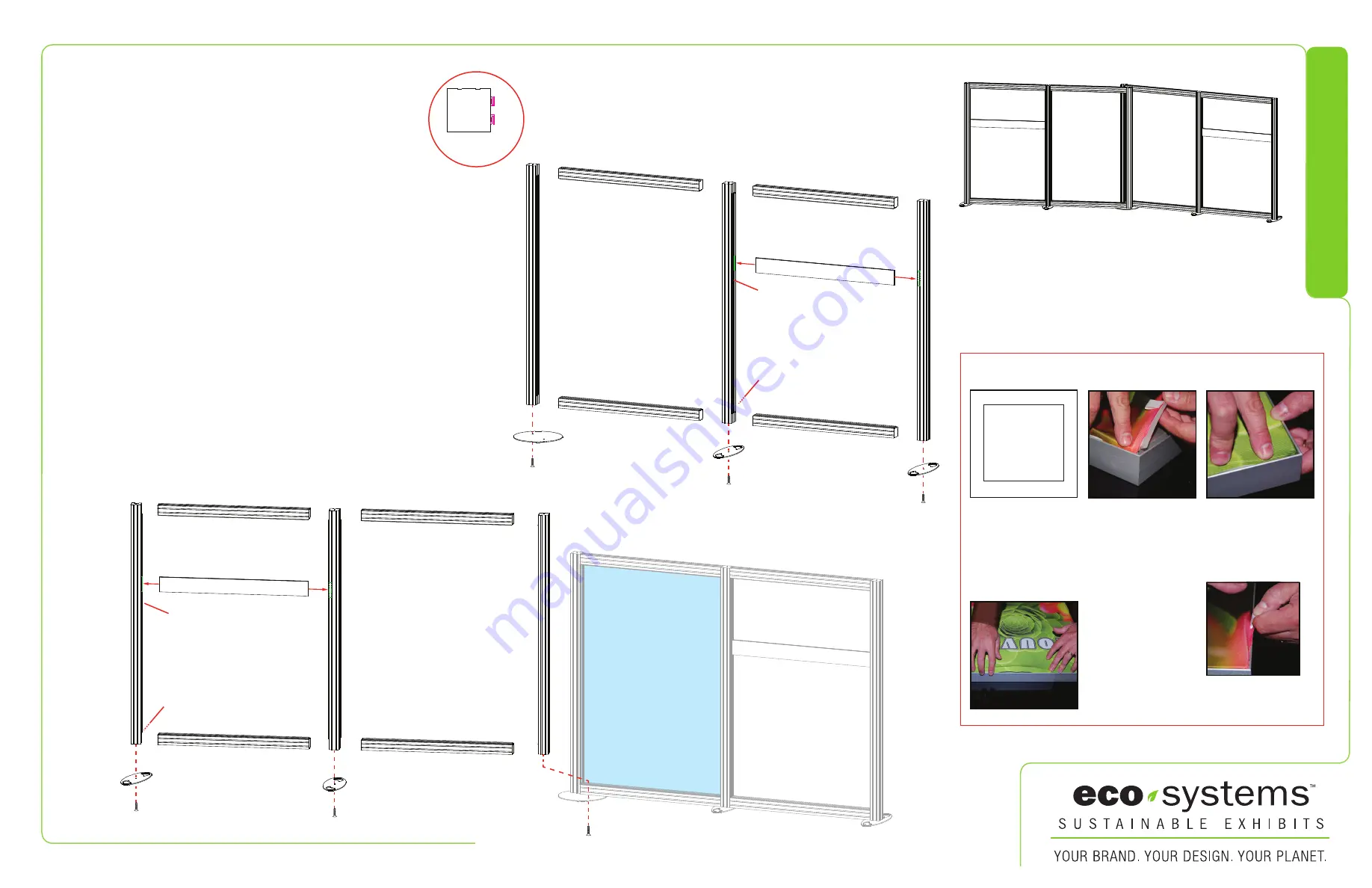
Steps:
1) Attach Base Plates [1A] to bottom of verticals [3,3A,8,8A]
using bolts.
2) Connect Oval Base Plate [1B] to bottom of vertical [6A].
3) Attach horizontals [2,2A,5,5A] between verticals [3,3A,6A].
4) Connect horizontal [4] to the S10 extrusions on verticals [3,3A]
5) Apply SEG Graphic to front only of assembly [3/5/5A/6A].
6) Connect vertical [11A] to Oval Base Plate [1B].
7) Attach horizontals [7,7A,10,10A] between verticals [8,8A,11A].
8) Connect horizontal [9] to the S10 extrusions on verticals [8,8A].
SEG Graphic Installation
Corner A
Corner D
Corner B
Corner C
It is important to first insert
graphic into each alternate
corner then to the sides of
the frame. If this is not done,
graphic will not fit into the
frame correctly.
Step 1
Insert corner A. Turn edge of
graphic so silicon welt is
perpendicular to face of
graphic. Insert narrow side
of welt with fabric to outside
into the channel. Repeat for
other side of this corner.
Step 2
Repeat Step 1 for opposite
corner C, then insert corner
B, followed by corner D, to
complete the installation of
the corners.
Graphic Removal
To remove the graphic from
the frame, locate the fabric
pull tab. Gently pull up on
the tab to remove the fabric.
Step 3
Once all corners are inserted,
press one silicon edge into
channel from corners and
work toward the center.
Make sure welt is fully inserted
into channel. Continue until
all sides are done. Smooth
out edges of graphic.
When assembled
1A
1A
1B
5
5A
2
2A
hole for wire
management
S10
S10
hole for wire
management
(back side)
3
6A
3A
4
Item
1A
1B
2/2A
3/3A
4
5/5A
6A
7/7A
8/8A
9
10/10A
11A
Qty.
4
1
1/1
1/1
1
1/1
1
1/1
1/1
1
1/1
1
Description
8”x22” Eco Leaf Oval Baseplate
18” Round Baseplate
56“w Q918 Horizontal Extrusion w/ TSP3
90”h Q918 Vertical Extrusion w/ TSP3 & S10
55.094”w Z140 Horizontal Extrusion
56“w Q918 Horizontal Extrusion w/ TSP3
90”h Q918 Vertical Extrusion w/ TSP3
56“w Q918 Horizontal Extrusion w/ TSP3
90”h Q918 Vertical Extrusion w/ TSP3 & S10
55.094”w Z140 Horizontal Extrusion
56“w Q918 Horizontal Extrusion w/ TSP3
90”h Q918 Vertical Extrusion w/ TSP3
1A
1A
1B
7
7A
10
10A
11A
6A
5A
2A
4
5
2
3A
3
8
8A
9
hole for wire
management
hole for wire
management
(back side)
Extrusion
Profile
Q918
TSP3
TSP3
SEG Graphic
S10
S10


