background image

ETS 73

0548-990-51---60g_2019.10.indd

A

A

A

A

A

A

!

0548-990/52g

Page 20 of 98

Mounting and operating instructions

4.3 

General

Warning:

The fastening bases must provide sufficient solidity. If necessary they have to be rein

-

forced by the appropriate means.

Attention:

The maximum admissible undulation of the fastening base is 1 mm. The drive me

-

chanism must be fastened without torsion and perpendicularly, using all the six fixing 

holes!

Warning:

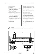
Tighten all the six M6 fixing screws (A) with a torque of 

10 Nm

!

Note:

Depending on the assembly situation of the drive mechanism, it may be advisable to 

install the program selector on the opposite side (in order to guarantee an optimal 

operating facility). Should this be required, the work must be carried out according to 

chapter "Electrical connections".

Note:

In cases where it is planned to integrate an open position stop piece into the drive 

mechanism (option), this stop piece must be mounted prior to the rod assembly (see 

instructions for option 0548-992/02 resp. 0548-992/52).

Note:

In case FLATSCANs are planned, they must be mounted according to chapter 13.9.

Summary of Contents for ETS 73

Page 1: ...0548 990 52g 2019 10 Swing door drive mechanism ETS 73 Mounting and operating instructions Original Com no Pos Construction year Operator Operating place...

Page 2: ...safety elements according to EN 16005 14 3 8 Maximum wind load capacity 15 4 MOUNTING 17 4 1 Preparation 17 4 2 Mounting versions 18 4 2 1 Rod assemblies narrow RS RG 18 4 2 2 Rod assemblies stainles...

Page 3: ...ker 63 6 4 2 Diagram sticker 63 6 5 Mount the drive mechanism covering 64 7 CONTROL 65 7 1 Main switch 65 7 2 Program selector 65 7 3 Operating modes 66 7 4 Adjustings 67 7 4 1 Motional parameters PAR...

Page 4: ...ng examples 89 13 1 7 Error display 90 13 2 KOMBI D BEDIX 91 13 3 Open position stop piece integrated in the drive mechanism 92 13 4 Connection plate for wooden door leaf normal rods 92 13 5 Mounting...

Page 5: ...ns must only be carried out by experts Experts are persons who based on their professional training and experience have sufficient knowledge in the field of powered windows doors and gates They are su...

Page 6: ...ding on the respective situation and authorization please ask your distribution agent Company portrait Homepage News Info News via E mail Product brochures Product presentation PowerPoint Submission t...

Page 7: ...the work 2 3 Safety regulations 2 3 1 Principles According to standard EN 16005 DIN 18650 describing the safety related requirements for automatic door systems a risk evaluation is to be carried out...

Page 8: ...d operated in dry rooms If this condition cannot be fulfilled the customer must provide sufficient protection from moisture The swing door drive mechanism ETS 73 must not be mounted within locations p...

Page 9: ...ive safety devices may not be disconnected in order to be able to continue the operation of the installation 2 3 4 Malfunctions If any malfunctions occur which might be detrimental to the safety of th...

Page 10: ...r C Spring unit for spring powered closing respectively opening D Direct current motor E Gear F Output shaft with eight pointed star for the connection of the rod assembly G Control H Main switch I Pr...

Page 11: ...le F Glider G Sliding rail Normal rods Sliding rods 3 3 Inverse application The swing door drive mechanism ETS 73 is also appropriate for inversed operation This particular function can be separately...

Page 12: ...e mechanisms are used which are connected via the CAN bus system Drive mechanism 2 Slave Drive mechanism 1 Master Earlier door leaf the first one to open the second one to close Delayed door leaf the...

Page 13: ...drive mechanism max 560 W Motor power rating 100 W Power supply external comsumer 24 VDC 10 2 A Torque output shaft 80 Nm permanent 240 Nm max Distance door hinge Output shaft lintel mounting 280 mm l...

Page 14: ...kg 131 170 kg 171 210 kg 211 250 kg EN 3 851 950 mm EN 4 951 1 100 mm EN 5 1 101 1 250 mm EN 6 1 251 1 400 mm EN 7 1 401 1 600 mm 4 4 3 2 2 3 3 2 2 1 2 1 1 1 1 2 1 1 1 1 1 1 1 1 0548 990 52g Page 14 o...

Page 15: ...P a 4 5 k m h 1 0 0 P a 4 0 k m h 8 0 P a 3 5 k m h 6 0 P a 2000 2100 2200 2300 2400 2500 2600 2700 2800 2900 3000 800 900 1000 1100 1200 1300 1400 1500 1600 8 0 k m h 3 2 0 P a 7 0 k m h 2 4 5 P a 6...

Page 16: ...1200 1300 1400 1500 1600 5 5 k m h 1 5 0 P a 5 0 k m h 1 2 5 P a 4 5 k m h 1 0 0 P a 4 0 k m h 8 0 P a 3 5 k m h 6 0 P a 3 0 k m h 4 5 P a 2 5 k m h 3 0 P a 0548 990 52g Page 16 of 98 Mounting and ope...

Page 17: ...n open position stop piece can be integrated into the drive me chanism itself 1 Check the free running movement of the door leaf Should it fail to move smoothly and silently or if it is out of balance...

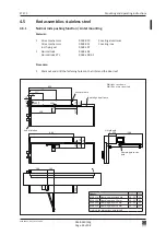
Page 18: ...548 164 01 pulling function Lintel mounting see chapter 4 4 2 Lintel depth 30 120 mm Drive mechanism 0548 030 alu 0548 031 inox Motor connector plug Standard X Inverse Y see chapter 4 1 Sliding rods 0...

Page 19: ...intel depth 30 70 mm 200 mm Drive mechanism 0548 030 alu 0548 031 inox Motor connector plug Standard Y Inverse X see chapter 4 1 Sliding rods 0548 134 620 mm pushing function 0548 105 01 KTL 620 mm 05...

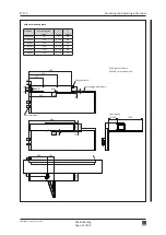
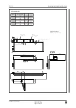
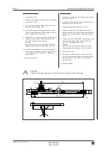
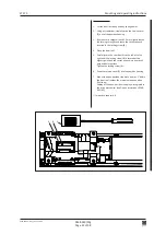
Page 20: ...all the six M6 fixing screws A with a torque of 10 Nm Note Depending on the assembly situation of the drive mechanism it may be advisable to install the program selector on the opposite side in order...

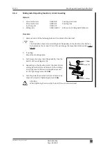
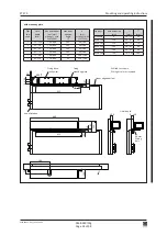
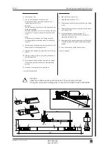
Page 21: ...m 0548 030 Covering aluminium Drive mechanism 0548 031 Covering inox incl fixing set 0548 107 1 Normal rods 0548 163 01 Procedure 1 Mark out and drill the fastening holes on the lintel and the door le...

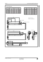
Page 22: ...0 52g Page 22 of 98 Mounting and operating instructions DIN right as shown DIN left mirror inverted Chassis profile Lintel depth Lower edge door frame Axis of rotation Options Axle extension mm mm mm...

Page 23: ...ng and operating instructions DIN right as shown DIN left mirror inverted Lintel depth DIBt checked Lower edge door frame Axis of rotation Options Axle extension mm mm mm Standard 0 3 21 0548 190 10 3...

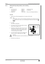
Page 24: ...e with the door leaf Fasten the rod arm B by means of the screws D Tightening moment 9 Nm forward to chapter 4 6 Attention Check the motional sequence of the door leaf The rods must not touch Inverse...

Page 25: ...nserted in the locking screw B 4 Close the door leaf 5 Carefully turn the cam disk A to the left or to the right until the locking screw B is located at the highest point and the socket wrench is in a...

Page 26: ...af Note The illustration shows a 46 mm sliding bolt Depending on the situation this bolt can be replaced by the version 18 mm This will change the respective dimensions by minus 28 mm 2 If existing Mo...

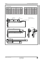
Page 27: ...edge door leaf 46 mm Sliding bolt Axis of rotation Lintel depth mm Min width door leaf mm without with FLATSCAN Max door opening angle A mm without with FLATSCAN 30 30 740 840 105 89 189 31 50 750 84...

Page 28: ...Bt che cked Lintel depth mm Min width door leaf mm without with FLATSCAN Max door opening angle A mm without with FLATSCAN 30 20 740 840 105 89 189 21 30 750 840 105 99 189 31 40 750 840 105 99 189 41...

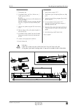
Page 29: ...n stop piece B into the sliding rail C 10 Slide the sliding rail C over the glider E and bolt it onto the door leaf 11 Screw down the open position stop piece B approx 5 before the door leaf reaches t...

Page 30: ...ustration shows the 18 mm sliding bolt Depending on the situation this bolt can be replaced by the version 46 mm This will change the respective dimensions by plus 28 mm 2 If existing Mount the mounti...

Page 31: ...ft mirror inverted Chassis profile Lintel depth Lower edge door frame 18 mm Sliding bolt Axis of rotation Lintel depth mm Min width door leaf mm Max door ope ning angle A mm 30 10 740 105 89 11 20 730...

Page 32: ...ower edge door frame 18 mm Sliding bolt Axis of rotation with mounting plate DIBt che cked Lintel depth mm Min width door leaf mm Max door ope ning angle A mm 30 0 740 105 89 1 10 730 105 79 11 20 720...

Page 33: ...t of the output shaft 15 9 Slide the open position stop piece B into the sliding rail C 10 Slide the sliding rail C over the glider E and bolt it onto the door leaf 11 Screw down the open position sto...

Page 34: ...Drive mechanism 0548 031 Covering inox incl fixing set 0548 107 1 Normal rods 0548 104 Normal rods KTL 0548 104 01 Procedure 1 Mark out and drill the fastening holes on the lintel and the door leaf D...

Page 35: ...ting arm D until the rod arm B forms a right angle with the door leaf Fasten the rod arm B by means of the screw F 9 Tighten all the screws forward to chapter 4 6 Inverse application 2 If existing Sub...

Page 36: ...et 0548 107 1 Sliding rods 0548 134 620 mm incl sliding bolts 14 38 mm Sliding rods KTL 0548 105 01 620 mm incl sliding bolts 14 38 mm Sliding rods 0548 105 02 830 mm incl sliding bolts 14 38 mm Proce...

Page 37: ...Clamping piece standard 51 73 86 0548 124 Clamping piece 13 mm 38 60 73 0548 125 Clamping piece 20 mm 71 93 106 0548 126 Clamping piece 50 mm 101 123 136 adjust the dimensions accordingly Lintel dept...

Page 38: ...etting screw I 5 While mounting the drive mechanism push the rota ting arm B back by the pre stressing angle of 15 6 Push the guide profile G over the glider C and hook it into the mounting profile E...

Page 39: ...t 0548 107 1 Sliding rods 0548 134 620 mm incl sliding bolts 14 38 mm Sliding rods KTL 0548 105 01 620 mm incl sliding bolts 14 38 mm Sliding rods 0548 105 02 830 mm incl sliding bolts 14 38 mm Proced...

Page 40: ...mm Min width door leaf mm Max door opening angle Rod assem blies art no A mm B mm C mm 30 20 740 105 0548 105 140 280 620 21 30 730 105 0548 105 130 280 620 31 40 720 105 0548 105 120 280 620 41 60 7...

Page 41: ...er the glider C and hook it into the mounting profile E 7 On both sides insert and screw down with 1 5 Nm the expansion element F 8 Snap in the covering caps D on both sides forward to chapter 4 6 Inv...

Page 42: ...minium Drive mechanism 0548 031 Covering inox incl fixing set 0548 107 1 Sliding rods 0548 105 02 830 mm incl sliding bolts 14 38 mm Procedure 1 Mark out and drill the fastening holes on the lintel an...

Page 43: ...ng instructions DIN left as shown DIN right mirror inverted Chassis profile Lintel depth Upper edge door leaf Clamping piece standard Sliding bolt 14 mm Axis of rotation Options 0548 114 Clamping piec...

Page 44: ...file E on the lintel 5 Screw down the rotating arm B parallel to the drive mechanism 6 Push the guide profile G over the glider C and hook it into the mounting profile E 7 On both sides insert and scr...

Page 45: ...ing out the automatic setting up procedure The setting values are only manda tory for fire protection and or escape way doors As a general rule the closing spring force can be reduced when setting the...

Page 46: ...52g Page 46 of 98 Mounting and operating instructions EN class Width of door leaf Normal rods Measure X Sliding rods pulling function Measure X Sliding rods pushing function Measure X Inverse applica...

Page 47: ...r in the operating mode MANUAL the door leaf is reliably engaged by the door lock the drive mechanism is equipped with a door slam function acceleration causing a forceful closing By means of the pote...

Page 48: ...intervenes approx 5 before reaching the closed position Under normal conditions it will not be necessary to change the default setting However in cases where in the de energized state or in the opera...

Page 49: ...outed below the chassis profile whereas the cables of the control and safety elements can be routed within the drive mechanism Procedure 1 If required break out the pre perforated flap on the side cov...

Page 50: ...ETS 73 0548 990 51 60g_2019 10 indd PE 1 2 PE L N PE 1 2 PE L N PE L N 0548 990 52g Page 50 of 98 Mounting and operating instructions Program selector further away from the door hinges Strain relief...

Page 51: ...2019 10 indd 47 22 22 28 614 28 670 0548 990 52g Page 51 of 98 Mounting and operating instructions 5 2 Cable layout 5 2 1 Lintel mounting Option Flexible power supply system 0548 209 Socket by custome...

Page 52: ...ication we advise to use an electric lock or a holding magnet which maintains the door leaf in the closed position and must answer the following require ments tested and homologated for escape and res...

Page 53: ...locks the motorized lock Functional performance Opening command Impulse and permanent command transmitted to motorised lock CONFIG Unlock IMPULS or PERMAN Locking latch opens Starting delay TDelay to...

Page 54: ...motorized daily release the seal as well as the board immediately behind it must be pierced and the lock must be restarted Attention Daily release is not allowed for fire safety doors Connect terminal...

Page 55: ...PARAMETER TDelay 0 MTS anti panic lock M 9300 with control unit KABA x lock X6 2 X6 5 X3 20 X3 21 CONFIG EL Fb N O PARAMETER TDelay 0 Fuhr autotronic 834 Fuhr autotronic 834P anti panic function for...

Page 56: ...Procedure 1 Switch on the mains supply switch on the side cover power up 2 Using the joystick adjust the display direction Move the joystick downward once the display direction is switched to a readab...

Page 57: ...ing up procedure Teach and validate by means of OK 10 Start the setting up procedure Teach validate by means of OK 11 Upon expiry of 10 seconds the setting up procedure Teach is auto matically initiat...

Page 58: ...ching The door leaf is closed at super slow speed The safety sensory system is active except during the teach in procedure Start the teach in from the open position This ensures the teach in of the ne...

Page 59: ...ct upon the Master single leaf operation Opening elements connected to Slave act upon the Master as well as on the Slave bi parting operation The safety elements SER and SES are connected to the respe...

Page 60: ...or leaves will be simultaneously opened i e that no opening delay is active The default value of AcSeq is 20 and thus sufficient for the majority of bi parting installations In cases where a mechanica...

Page 61: ...or is used start with a AcSeq of 90 afterwards AcSeq can be reduced 6 Configuration of the Slave drive mechanism DubleD SlaveA AoSeq desired time lag of the opening angle Control 1 Check the display o...

Page 62: ...rol 1 Check the display of the Master control unit to see if a small black w is visible on the first level connection existing Note A small white w indicates Missing connection 2 Transmit a Key comman...

Page 63: ...ne Way GND EL24V GND EL COM EL NO EL NC EL Fb 1 2 3 4 5 6 7 8 9 10 11 12 13 14 15 16 17 18 19 20 21 22 23 24 25 26 27 28 29 30 31 32 EmA EmB D Bedix D Bedix SE24V SEStop SETest GND SE24V SERev SETest...

Page 64: ...e 64 of 98 Mounting and operating instructions 6 5 Mount the drive mechanism covering Material 1 Covering 0548 400 Aluminium 1 Covering accessories 0548 143 Aluminium or 1 Covering 0548 303 Stainless...

Page 65: ...ting modes AUTOMATIC NIGHT OPEN MANUAL and EXIT The presently enabled operating mode is identified by the illuminated key Note In the event of a pending fatal error alle the keys shortly flash up Key...

Page 66: ...tside OPEN The door leaf is automatically opened and remains in the OPEN position MANUAL The drive mechanism and the control elements are switched off The door leaf can be manually opened The door lea...

Page 67: ...elay is 0 Door rectification time time press close Pressing force during locking force lock only effective if TLock is 0 Accelerating function force slam Obstacle detection optimized for exterior door...

Page 68: ...t only visible if relay PCB 0 is plugged in Parametrizable relay output 3 on optional PCB 1 relay contact only visible if relay PCB 0 is plugged in Parametrizable relay output 4 on optional PCB 1 rela...

Page 69: ...ions Parameter Description Closing sequence role Master Slave and interlock side A B Current delay angle for opening sequence control Slave only visible if DubleD is active Current delay angle for clo...

Page 70: ...ETS 73 0548 990 51 60g_2019 10 indd 0548 990 52g Page 70 of 98 Mounting and operating instructions 7 4 4 Menu navigation Password protected...

Page 71: ...O Push and Go 2nd display line at the bottom left hand side the presently enabled operating mode is displayed a frame around the symbol indicates the overriding operat ing mode m means closing sequenc...

Page 72: ...r 13 8 ERROR ACTIVE Pending active errors The pending active errors are displayed in a list This list is updated at the end and the latest additions appear during the next passage A0 indicates the lat...

Page 73: ...sm continues to beep Teach OK is validated by means of OK and aborted by any other joystick movement The setting up procedure can be canceled by means of the D BEDIX C key Setting of the opening angle...

Page 74: ...far as these are included in the installation Warning To avoid jeopardizing the safety of persons any defective safety elements may not be disonnected in order to continue the operation of the instal...

Page 75: ...3 seconds1 x x Activation escape way detector 1 5 m in front of the door1 x x Minimum escape way width1 x x Maximum opening force at Break Out leaf 220 N 1 m from floor x x Safety elements Reversing s...

Page 76: ...covering of the drive mecha nism 2 Check all the cable connections 3 Normal rods Separate the rod arm B from the rotating arm A Pull the spherical joint C apart 4 Check the free running movement of t...

Page 77: ...and carefully check if the door closes in a cushioned manner If not replace the hardware If yes check correct the friction of the door leaf and the pre stressing of the closing spring Prior to the clo...

Page 78: ...tacle Move the door leaf to the target position Permanent H A Restart after 60 s 02 Obstacle in closing direction E16 01 Temperature Temperature on output level has reached 81 C Respect the applicaito...

Page 79: ...cking time Reaction E60 00 Relay PCB 0 Option PCB has been remo ved its address changed or become defective Check if the option is provided If defective Replace or remove from the configu ration Note...

Page 80: ...mmands inside outside etc are ignored Change the operating mode Correct the cabling of the opening elements LED SE safety element yellow is not lighted LED OE opening command blue is not lighted despi...

Page 81: ...ans of an USB memory stick Note Not all the USB memory sticks can be used We thus recommend a previous testing of their function together with the ETS 73 9 3 1 Preparation The USB stick must contain a...

Page 82: ...s approx 1 minute Watch the LED display on the ocntrol unit 9 3 3 LED display on the control The display of the functions is ensured via three LEDs on the control PCB SOK Green USB Loader started OE B...

Page 83: ...mechanism will not be used during at least 1 month it is recommended to pull out the mains plug For taking the installation back into operation all you have to do is to plug in the mains cable and sel...

Page 84: ...THE INSTALLATION An ecologically acceptable disposal of the installation is ensured if the different materials are separated and recycled No particular measures are required for the protection of the...

Page 85: ...RS 0548 164 01 Sliding rods RG incl sliding rail 650 mm 0549 115 Connection plate for wooden door leaf compl normal rods Option 0548 190 01 Axle extension RG RS 10 mm incl Tuflok screw 0548 191 01 Ax...

Page 86: ...Only one D BEDIX can be connected per door installation 13 1 1 Keys C key Cancel Exit the menu Invalidate entry OK key Confirm the selection Confirm the entry Arrow keys Navigate within the menus Sho...

Page 87: ...ed to the operating mode NIGHT from any random operating mode the internal radar will still remain active during the programmed time TdNigt EXIT OPEN The installation is opened and remains in the open...

Page 88: ...y Description PARAMETER Setting the motional parameters CONFIG Setting the functionalities DOUBLE DOOR Setting the closing sequence and interlock function DIAGNOSTICS Diagnostic tool ERROR ACTIVE Acti...

Page 89: ...ctuation of both arrow keys access to the menu level By means of the arrow key select BLOCK Confirm with the C key and the right hand arrow key 13 1 6 Setting examples Changing the operating mode Sele...

Page 90: ...s of the arrow key change the value Confirm with the OK key Teach Completely close the door leaf Short simultaneous actuation of the arrow keys access to the menu level By means of the arrow key selec...

Page 91: ...ntains a key operated switch round or profile cylinder with the following function Lockout of the KOMBI D BEDIX against unautho rized use Free Locked If this lockout is enabled all the keys are shortl...

Page 92: ...door leaf from being damaged in the manual operating mode As an option an open position stop piece can be integrated into the drive mechanism itself 13 4 Connection plate for wooden door leaf normal r...

Page 93: ...98 Mounting and operating instructions 13 5 Mounting plate In cases where the fastening holes provided in the chassis profile of the ETS 73 cannot be used the mounting plate 0548 358 can be used as an...

Page 94: ...covering For bi parting installations the two drive mechanisms can be optically connected by inserting an intermediate covering piece Set with drive mechanism covering 1 9 m Alu 0548 214 or Set with d...

Page 95: ...Addr0 or Addr1 2 Switch on the main installation swtich on the drive mechanism the relay PCB is automatically identified The identified relay PCB is displayed as follows in the diagnostic menu R0 Addr...

Page 96: ...ve mechanism all the transmitters need to be programmed with the same code which is transmitted from the standard transmitter to all the additional transmitters On the other hand several drive mechani...

Page 97: ...cted among each other see wiring diagram in the appendix If a door radar is mounted directly above the FLATSCAN it is compulsory to mount the weather canopy for screening against radar mocrowaves Lint...

Page 98: ...and operating instructions 14 APPENDIX The following documents are added as an appendix to this instructions Wiring diagram E4 0141 713_ECO Wiring diagram Relay PCB E4 0141 715_ECO Wiring diagram Flat...

Page 99: ......

Page 100: ......

Page 101: ......

Page 102: ......

Page 103: ......

Page 104: ......

Page 105: ......

Page 106: ......

Page 107: ......

Page 108: ......

Page 109: ......

Page 110: ......

Page 111: ......

Page 112: ......

Reviews: