ETS 73
0548-990-51---60g_2019.10.indd
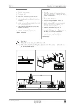
D
F
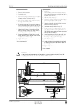
14 Nm
E
Loctite 243
G
5 Nm
0548-990/52g
Page 30 of 98
Mounting and operating instructions
4.4.3
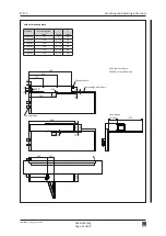
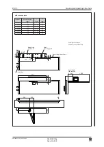
Sliding rods RG pushing function / Lintel mounting
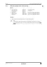
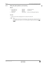
Material:
1 Drive mechanism
0548-030
Covering aluminium
Drive mechanism
0548-031
Covering inox
incl. fixing set
0548-107
1 Sliding rods
0548-164/01
650 mm incl. sliding bolts 18/46 mm
Procedure:
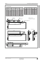
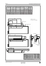
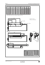
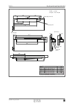
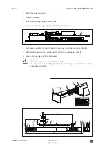
1. Mark out and drill the fastening holes on the lintel and the door leaf.
Note:
The illustration shows the 18 mm sliding bolt. Depending on the situation, this bolt can
be replaced by the version 46 mm. This will change the respective dimensions by plus
28 mm
.
2. If existing:
Mount the mounting plate.
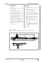
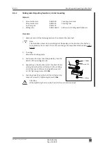
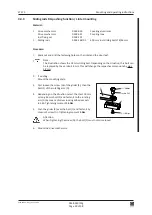
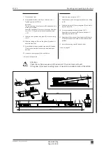
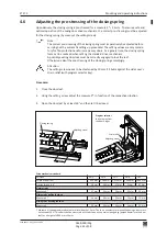
3. First loosen the screw (G) of the glider (E), then the
bolt (F) of the rotating arm (D).
4. Depending on the situation, select the short 18 mm
or long 46 mm bolt (F) and fasten it to the rotating
arm (D) by means of screw locking adhesive Locti
-
te 243: Tightening moment
14 Nm
.
5. Push the glider (E) over the bolt (F) and fasten it by
means of screw (G): Tightening moment
5 Nm
.
Attention:
When tightening the screw (G), the bolt (F) must not come loose!
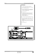
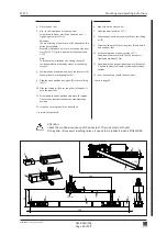
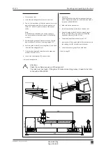
6. Mount the drive mechanism.


